Understanding Seamless MPLS
Seamless MPLS deploys a Border Gateway Protocol (BGP) LSP across the access, aggregation, and core layers to implement end-to-end service transmission through a tunnel. An LSP can be established between any two nodes on a seamless MPLS network to transmit service packets upstream and downstream. This network architecture ensures high service scalability, while only needing to deploy signaling protocols at service access points.
Seamless MPLS supports the following three networking solutions:
Intra-AS Seamless MPLS: The access, aggregation, and core layers are within a single AS. Intra-AS seamless MPLS applies to mobile bearer networks.
Inter-AS Seamless MPLS: The access and aggregation layers are within a single AS, and the core layer is in another AS. Inter-AS seamless MPLS transmits enterprise services.
Intra-AS Seamless MPLS
Control plane
Deploy routing protocols.
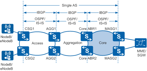
In Figure 1, routing protocol deployment on devices is as follows:An IGP (IS-IS or OSPF) is enabled on devices at each of the access, aggregation, and core layers to implement intra-AS connectivity.
- For example, the path CSG1 -> AGG1 -> core ABR1 -> MASG1 is used. An IBGP peer relationship is established between each pair of the following devices:
- CSG and AGG
- AGG and core ABR
- Core ABR and MASG
The AGG and core ABR are configured as RRs so that the CSG and MASG can obtain routes destined for each other's loopback addresses.
The AGG and core ABR set the next hop addresses in BGP routes to their own addresses to prevent advertising unnecessary IGP area-specific public routes.
Deploy tunnels.
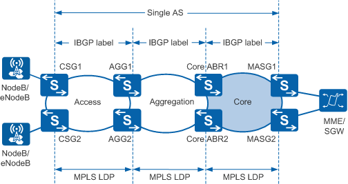
In Figure 2, tunnel deployment is as follows:A public network tunnel is established using LDP in each IGP area.
- For example, the path CSG1 -> AGG1 -> core ABR1 -> MASG1 is used. An IBGP peer relationship is established between each pair of the following devices:
- CSG and AGG
- AGG and core ABR
- Core ABR and MASG
These devices are enabled to advertise labeled routes and assign labels to BGP routes that match a specified routing policy. After the devices exchange labeled BGP routes, an E2E BGP LSP between the CSG and MASG is established.
Forwarding plane
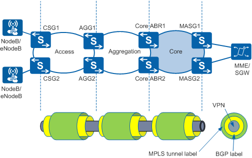
Figure 3 illustrates the forwarding plane of the intra-AS seamless MPLS networking. Seamless MPLS primarily transmits VPN packets. The following example demonstrates how VPN packets, including labels and data, are transmitted from a CSG to an MASG along the path CSG1 -> AGG1 -> core ABR1 -> MASG1. The process is as follows:The CSG adds a BGP label and an MPLS tunnel label in sequence to each VPN packet and forwards the packets to the AGG.
The AGG removes the access-layer MPLS tunnel labels from the packets and swaps the existing BGP labels for new labels. The AGG adds an aggregation-layer MPLS tunnel label to each packet. The AGG then forwards packets to the core ABR. If the penultimate hop popping (PHP) function is enabled on the AGG, the CSG has removed the MPLS tunnel labels from the packets, and therefore, the AGG receives packets without MPLS tunnel labels.
The core ABR removes aggregation-layer MPLS tunnel labels from the VPN packets and swaps the existing BGP labels for new labels. The AGG adds a core-layer MPLS tunnel label to each packet. It then forwards the packets to the MASG.
The MASG removes MPLS tunnel labels and BGP labels from the VPN packets. If the PHP function is enabled on the MASG, the core ABR has removed the core-layer MPLS tunnel labels from the packets; therefore, the MASG receives packets without MPLS tunnel labels. The VPN packet transmission along the intra-AS seamless MPLS tunnel is complete.
Inter-AS Seamless MPLS
Control plane
Deploy routing protocols.
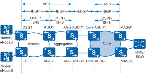
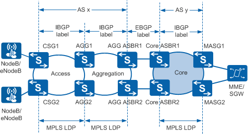
In Figure 4, routing protocol deployment on devices is as follows:An IGP (IS-IS or OSPF) is enabled on devices at each of the access, aggregation, and core layers to implement intra-AS connectivity.
- For example, the path CSG1 -> AGG1 -> AGG ASBR1 -> core ASBR1 -> MASG1 is used. A BGP peer relationship is established between each pair of the following devices:
- CSG and AGG
- AGG and AGG ASBR
- AGG ASBR and core ASBR
- Core ASBR and MASG
An EBGP peer relationship between the AGG ASBR and core ASBR is established, and IBGP peer relationships between other devices are established.
The AGG is configured as an RR so that IBGP peers can exchange BGP routes, and the CSG and MASG can obtain BGP routes destined for each other's loopback addresses.
If the AGG ASBR and core ASBR are indirectly connected, an IGP neighbor relationship between them must be established to implement inter-area connectivity.
Deploy tunnels.
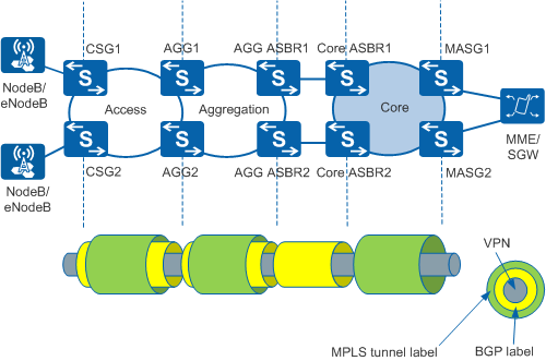
In Figure 5, tunnel deployment is as follows:A public network tunnel is established using LDP in each IGP area.
The CSG, AGG, AGG ASBR, and core ASBR are enabled to advertise labeled routes and assign labels to BGP routes that match a specified routing policy. After the devices exchange labeled BGP routes, a BGP LSP between the CSG and core ASBR is established.
- Either of the following tunnel deployment methods in the core area can be used:
A BGP LSP between the core ASBR and MASG is established. This BGP LSP and the BGP LSP between the CSG and core ASBR are combined into an E2E BGP LSP. The route to the MASG's loopback address is installed into the BGP routing table and advertised to the core ASBR using the IBGP peer relationship. The core ASBR assigns a label to the route and advertises the labeled route to the AGG ASBR.
No BGP LSP between the core ASBR and MASG is established. The core ASBR runs an IGP to learn the route destined for the MASG's loopback address and installs the route to the routing table. The core ASBR assigns a BGP label to the route and associates the route with an intra-AS tunnel. The BGP LSP between the CSG and core ASBR and the MPLS tunnel in the core area are combined into an E2E tunnel.
Forwarding plane
Figure 6 illustrates the forwarding plane of the inter-AS seamless MPLS networking with a core-layer BGP LSP established. Seamless MPLS primarily transmits VPN packets. The following example demonstrates how VPN packets, including labels and data, are transmitted from a CSG to an MASG along the path CSG1 -> AGG1 -> AGG ASBR1 -> core ASBR1 -> MASG1.The CSG adds a BGP label and an MPLS tunnel label in sequence to each VPN packet and forwards the packets to the AGG.
The AGG removes the access-layer MPLS tunnel labels from the packets and swaps the existing BGP labels for new labels. The AGG adds an aggregation-layer MPLS tunnel label to each packet. The AGG then forwards the packets to the AGG ASBR. If the PHP function is enabled on the AGG, the CSG has removed the MPLS tunnel labels from the packets; therefore, the AGG receives packets without MPLS tunnel labels.
The AGG ASBR then removes the MPLS tunnel labels from the packets and swaps the existing BGP label for a new label in each packet. It then forwards the packets to the core ASBR. If the PHP function is enabled on the AGG ASBR, the AGG has removed the MPLS tunnel labels from the packets, and therefore, the AGG ASBR receives packets without MPLS tunnel labels.
After the core ASBR receives the packets, it swaps a BGP label for a new label and adds a core-layer MPLS tunnel label to each packet. It then forwards the packets to the MASG.
The MASG removes MPLS tunnel labels, BGP labels, and VPN labels from the packets. If the PHP function is enabled on the MASG, the core ASBR has removed the MPLS tunnel labels from the packets; therefore, the MASG receives packets without MPLS tunnel labels. The VPN packet transmission along the inter-AS seamless MPLS tunnel is complete.
Figure 6 Forwarding plane for the inter-AS seamless MPLS networking with a BGP LSP established in the core area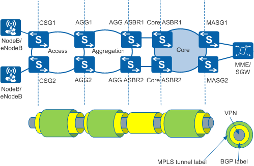
Figure 7 illustrates the forwarding plane for the inter-AS seamless MPLS networking without a BGP LSP established in the core area. The process of transmitting packets on this network is similar to that on the network with a BGP LSP established. The difference is that without a BGP LSP in the core area, the core ASBR only removes BGP labels from packets, while adding MPLS tunnel labels to these packets.
