SEP Implementation Mechanisms
Neighbor Negotiation Mechanism
After an interface is added to a SEP segment, the interface and its neighbor exchange Hello packets to initiate a neighbor relationship. After neighbor negotiations succeed, the two interfaces continue to exchange Hello packets to detect their neighbor status.
Neighbor negotiations are bidirectional and therefore prevent unidirectional links. Interfaces at both ends of a link must send Hello packets to each other for status confirmation. If an interface does not receive a Hello packet from an interface within a specified interval, the interface considers the other to be Down.
Neighbor negotiations provide information required to obtain the SEP segment topology. Interfaces form a complete SEP segment by establishing neighbor relationships through neighbor negotiations.
Synchronization of SEP LSA Databases and Topology Display
Synchronization of SEP link state advertisement (LSA) databases
After neighbor negotiations are complete, devices in a SEP segment enter the LSA database synchronization phase and periodically send LSAs. After a device receives LSAs from other devices, the device updates its LSA database. This ensures consistency in the LSA databases of all devices in the SEP segment.
If a device does not receive LSAs within three LSA transmission intervals, the device will age the database that saves the LSAs of the other devices in the SEP segment.
When a faulty device in a SEP segment recovers, the device must obtain topology information from other devices (peer and other devices) in the SEP segment and send LSA request packets to the devices. After receiving LSA request packets from the device, neighboring interfaces reply with LSA ACK packets that contain the latest link state information.
SEP segment topology display
The topology display function allows you to view the topology that has the highest network connectivity of any device in a SEP segment. Link state synchronization ensures that all devices in a SEP segment display the same topology.
Table 1 describes different types of SEP segment topologies.
Table 1 Types of SEP segment topologies Topology Type
Description
Constraint
Ring topology
Each interface in a SEP segment has a neighboring interface in Up state and a brother interface. Each node has two interfaces in the SEP segment.
If the primary edge interface is elected on a ring, the primary edge interface is listed first in the topology information displayed on each interface.
If the secondary edge interface is elected, it is listed first in the topology information displayed on each interface
Linear topology
All topologies except ring topologies are linear topologies.
For interfaces at both ends of a link:If one interface functions as the primary edge interface, the primary edge interface is listed first in the topology information displayed on each interface.
If the secondary edge interface is elected, the secondary edge interface is listed first in the topology information displayed on each interface.

The constraints listed in Table 1 ensure that each node in a ring or linear topology displays the same topology information.
Primary Edge Interface Election
Only no-neighbor, primary, and secondary edge interfaces can participate in primary edge interface election.
If only one interface on a node has SEP enabled, you must set the role of the interface to edge so that the interface can function as an edge interface.
Common interfaces do not participate in primary edge interface election. Only P1 on LSW1 and P1 on LSW5 participate in primary edge interface election.
If P1 on LSW1 and P1 on LSW5 have the same role, P1 with a larger MAC address is elected as the primary edge interface.
After the primary edge interface is selected, it periodically sends primary edge interface election packets without waiting for successful neighbor negotiations. A primary edge interface election packet contains the interface role (primary edge interface, secondary edge interface, or common interface), bridge MAC address of the interface, interface ID, and integrity of the topology database.

- P1 on LSW1 and P1 on LSW5 receive fault notification packets, and P1 on LSW1 becomes the secondary edge interface.
- P1 on LSW5 does not receive primary edge interface election packets within a specified period, and P1 on LSW1 becomes the secondary edge interface.
Two secondary edge interfaces exist in the SEP segment and periodically send primary edge interface election packets.
When all link faults in the SEP segment are rectified, the two secondary edge interfaces can receive primary edge interface election packets and elect a new primary edge interface within a configured interval (1s by default).
Specifying an Interface to Block
A blocked interface is typically one of the two interfaces that complete neighbor negotiations last. You can specify an interface to block according to network requirements. The preemption mechanism must take effect before a specified interface preempts to be the blocked interface.
The following describes the interface blocking mode and preemption mechanism.
Interface blocking mode
You can configure the interface blocking mode to specify a blocked interface. Table 2 describes interface blocking modes.
Table 2 Interface blocking mode Interface Blocking Mode
Description
Specify the interface with the highest priority as the blocked interface.
SEP compares interface priorities by:Comparing configured interface priority values. A larger value indicates a higher priority.
Comparing bridge MAC addresses of interfaces with same priority values. A smaller bridge MAC address indicates a higher priority.
Comparing interface numbers of interfaces with identical bridge MAC addresses. A smaller interface number indicates a higher priority.
Specify the interface in the middle of a SEP segment as the blocked interface.
-
Specify a blocked interface based on the configured hop count.
SEP sets the hop count of the primary edge interface to 1 and the hop count of the neighboring interface of the primary interface to 2. Hop counts of other interfaces increase by steps of 1 in the downstream direction of the primary edge interface.
Specify a blocked interface based on the device and interface names.
After SEP is configured, the names of the device and interface determine the interface to be blocked. Before specifying an interface to be blocked, run the display command to view the current ring topology and all interfaces and then specify the device and interface names.
If multiple interfaces on the ring have the same device and interface names, SEP blocks the interface nearest to the primary edge interface in the topology.
NOTE:If you change the device name or interface name after specifying the interface to block, the interface cannot preempt to be the blocked interface.
Preemption
After the interface blocking mode is specified, you can configure the preemption mode to determine whether an interface will be blocked. Table 3 describes the preemption modes.Table 3 Preemption mode Preemption Mode
Description
Non-preemption
When all link faults are rectified or the last two interfaces enabled with SEP complete neighbor negotiations, interfaces send blocking status packets to each other. The interface with the highest priority is then blocked and the other interfaces enter the Forwarding state.
Preemption
NOTE:Preemption can only be implemented on the device where the primary edge interface or no-neighbor primary edge interface resides.
Preemption is classified into delayed preemption and manual preemption.
Delayed preemption
After all the faulty interfaces recover, the edge interfaces no longer receive fault notification packets. If the primary edge interface does not receive fault advertisement packets within 3 seconds, it starts the delay timer. After the delay timer expires, nodes in the SEP segment start blocked interface preemption.
Manual preemption
When the link status databases of the primary and secondary edge interfaces are complete, the primary edge interface or brother interface of the no-neighbor primary edge interface sends preemption packets to block a specified interface. The specified interface then sends blocking status packets to request the previously blocked interface to transition to the Forwarding state.
NOTE:Preemption can only be implemented on the device where the primary edge interface or no-neighbor primary edge interface resides.
Only two interfaces on a device can be added to the same SEP segment. If one interface is the no-neighbor primary edge interface, the other interface is the brother interface of the no-neighbor primary edge interface.
If the brother interface is blocked, it does not need to send preemption packets.
If the brother interface is unblocked, it must send preemption packets.
SEP Topology Change Notification
SEP considers that the topology of a SEP-enabled network changes depending on certain situations. Table 4 describes situations of SEP topology change notification.
Situation of SEP Topology Change Notification |
Description |
|---|---|
An interface fault occurs. |
An interface fault can be a link fault or neighboring interface fault. If an interface (in the SEP segment) is in Forwarding state and receives a fault advertisement packet, the device must send a Flush-Forwarding Database (Flush-FDB) packet through the interface to notify other nodes that there is a change in topology |
The fault is rectified and the preemption function takes effect. |
After faults occur in the SEP segment and the last faulty interface recovers, the blocked interface is preempted and the topology is considered changed. Preemption is triggered by the primary edge interface. When an interface in a SEP segment receives a preemption packet from the primary edge interface, the interface must send Flush-FDB packets to notify other nodes in the SEP segment that there is a change in topology. |
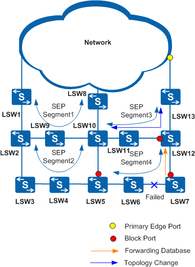
The topology change notification function is configured on devices that connect an upper-layer network and a lower-layer network. If the topology of one network changes, devices affected inform the other network of the change.
Table 5 lists the scenarios in which topology changes are reported.
SEP Topology Change Notification |
Scenario |
Description |
Solution |
|---|---|---|---|
Topology change notification from a lower-layer network to an upper-layer network |
A SEP network is connected to an upper-layer network that runs other features such as SEP, STP, Smart Link and RRPP. |
|
Configure the SEP topology change notification function. |
A host is connected to a SEP network using a Smart Link group. |
During an active/standby switchover of member interfaces in the Smart Link group, the host sends a Smart Link Flush packet to notify connected devices in the SEP segment of the switchover. If connected devices in the SEP segment cannot identify the Smart Link Flush packet, traffic is interrupted. |
Enable the edge devices in the SEP segment to process Smart Link Flush packets. |
|
Topology change notification from an upper-layer network to a lower-layer network |
A SEP network is connected to an upper-layer network where CFM is deployed. |
If a fault occurs on the upper-layer network, the topology of that network changes but the lower-layer network is unable to detect the change. As a result, traffic is interrupted. |
Configure association between SEP and CFM. In Figure 3, association between SEP and CFM is configured on LSW1. |
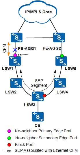
In Figure 3, association between SEP and CFM is configured on LSW1 in the SEP segment. When CFM detects a fault on the network at the aggregation layer, LSW1 sends a CCM to notify the Operation, Administration, and Maintenance (OAM) module of the fault. The SEP status of the interface associated with CFM then changes to Down.
The interface associated with CFM is in the SEP segment. If this interface goes Down, LSW2 must send a Flush-FDB packet to notify other nodes of the change in topology. After LSW3 receives the Flush-FDB packet, the blocked interface on LSW3 is unblocked and enters the Forwarding state. This interface sends a Flush-FDB packet to instruct other nodes in the SEP segment to update their MAC address tables and ARP tables. The lower-layer network can then detect the faults on the upper-layer network, ensuring reliable service transmission.
Suppression of SEP TC Notification Packets
- A link becomes disconnected transiently.
- A SEP segment is attacked by invalid TC notification packets.
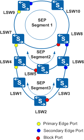
There are multiple SEP rings.
Figure 4 shows a networking scenario with three SEP rings. If the topology of SEP segment 3 changes, the number of TC notification packets doubles and SEP segment 2 is flooded with these packets. Each time TC notification packets pass through a SEP segment, its number doubles.
Configure a device to only process one of the TC notification packets that carry the same source address.
Configure a device to process a specified number of TC notification packets within a specified period. By default, three TC notification packets with different source addresses are processed in 2s.
Avoid having more than three SEP rings.
SEP Multi-Instance
In common SEP networking shown in Figure 5, a physical ring network can be configured with only one SEP segment in which only one interface can be blocked.
If an interface in a complete SEP segment is blocked, all service data is transmitted only along the path where the primary edge interface is located. The path where the secondary edge interface is located remains idle, wasting bandwidth.
SEP multi-instance allows two SEP segments to be configured on a physical ring. Each SEP segment independently detects the completeness of a physical ring and blocks or unblocks interfaces without affecting the other.
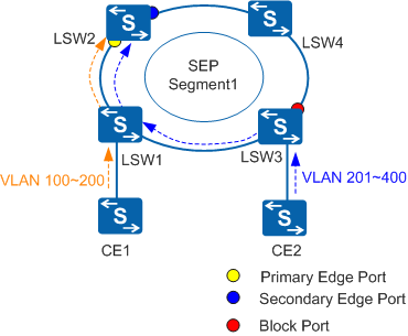
A physical ring may contain one or two SEP segments. Each SEP segment needs to be configured with a protected instance, each protected instance indicating a VLAN range. The topology calculated by a SEP segment is only valid for that SEP segment.
After different protected instances are configured for SEP segments and the mapping between protected instances and VLANs is set, a blocked interface is only valid for the VLANs protected by the SEP segment where the blocked interface resides. Data traffic for different VLANs can be transmitted along different paths. This implements traffic load balancing and link backup.
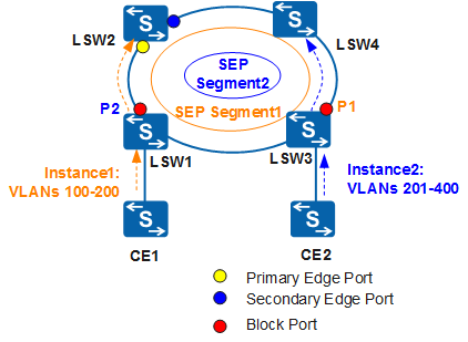
- Protected instance 1 is configured in SEP segment 1 to protect the data from VLAN 100 to VLAN 200. The data is transmitted along path LSW1 -> LSW2. As the blocked interface in SEP segment 2, P2 blocks only the data from VLAN 201 to VLAN 400.
- Protected instance 2 is configured in SEP segment 2 to protect the data from VLAN 201 to VLAN 400. The data is transmitted along path LSW3 -> LSW4. As the blocked interface in SEP segment 1, P1 blocks only the data from VLAN 100 to VLAN 200.
When a node or link fault occurs, each SEP segment calculates its own topology independently, and the nodes in each SEP segment update their own LSA databases.
In Figure 7, a fault occurs on the link between LSW3 and LSW4. The link fault does not affect the transmission path for the data from VLAN 100 to VLAN 200 in SEP segment 1, but blocks the transmission path for the data from VLAN 201 to VLAN 400 in SEP segment 2.
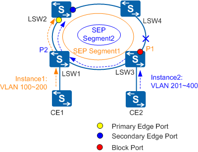
After the link between LSW3 and LSW4 becomes faulty, LSW3 starts to send LSAs to instruct the other devices in SEP segment 2 to update their LSA databases, and the blocked interface enters the Forwarding state. After the topology of SEP segment 2 is recalculated, the data from VLAN 201 to VLAN 400 is transmitted along path LSW3 -> LSW1 -> LSW2.
After the link between LSW3 and LSW4 recovers, the devices in SEP segment 2 perform delayed preemption. After the preemption delay expires, P1 becomes the blocked interface again, and sends LSAs to instruct the other devices in SEP segment 2 to update their LSA databases. After the topology of SEP segment 2 is recalculated, the data from VLAN 201 to VLAN 400 is transmitted along path LSW3 -> LSW4.