Application Scenarios for Traffic Suppression
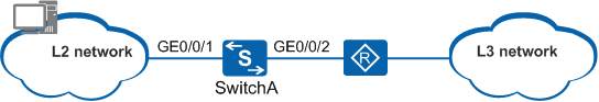
As shown in Figure 1,
- Traffic suppression can be configured in a VLAN on a Layer 2 network device to limit the rates of broadcast packets in the VLAN.
- Switch A is connected to a Layer 2 network and a router. To limit the rates of broadcast, unknown multicast, and unknown unicast packets forwarded by the Layer 2 network, configure traffic suppression on the Layer 2 Ethernet interface GE0/0/1 of Switch A. To limit the rates of known multicast and known unicast packets forwarded by the Layer 2 and Layer 3 network, configure traffic suppression on the Ethernet interface GE0/0/1 and GE0/0/2 of Switch A.
- You can also configure Switch A to block the outgoing broadcast, unknown multicast, and unknown unicast packets on GE0/0/1 to ensure Layer 2 network security.