Application Scenarios for MSTP
Application of MSTP
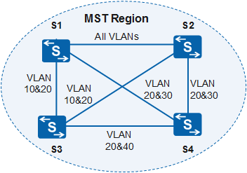
MSTP allows packets in different VLANs to be forwarded by using different spanning tree instances. An example of a network using MSTP is shown in Figure 1. The network is configured in the following ways:
All devices on the network belong to the same MST region.
VLAN 10 packets are forwarded within MSTI 1.
VLAN 30 packets are forwarded within MSTI 3.
VLAN 40 packets are forwarded within MSTI 4.
VLAN 20 packets are forwarded within MSTI 0.
In Figure 1, S1 and S2 are devices at the aggregation layer, and S3 and S4 are devices at the access layer. Traffic from VLAN 10 and VLAN 30 is terminated by aggregation devices, and traffic from VLAN 40 is terminated by the access device. Therefore, S1 and S2 can be configured as the roots of MSTI 1 and MSTI 3, and S3 can be configured as the root of MSTI 4.
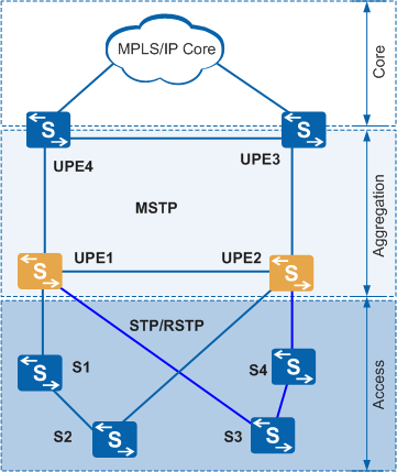
Application of MSTP Multi-process
In Figure 2, the UPEs are connected to each other through Layer 2 links and enabled with MSTP. The rings connected to the UPEs must be independent of each other. The devices on the rings connected to the UPEs support only RSTP, not MSTP.
After MSTP multi-process is enabled, each MSTP process corresponds to a ring connected to the UPE. STP on each ring calculates a tree independently.