VLL Fundamentals
Basic VLL Architecture
VLL transparently transmits Layer 2 data packets from customer edge (CE) devices over tunnels and provides P2P L2VPN service for users.
The basic VLL architecture consists of three components: attachment circuits (AC), virtual circuits (VC), and tunnels. Pseudo wire (PW) is also a common term used in the VLL service. Figure 1 shows the basic VLL architecture.
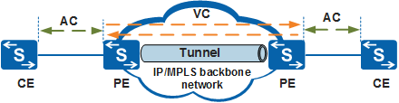
Component |
Full Name |
Description |
|---|---|---|
AC |
Attachment Circuit |
A connection between a customer and an ISP, namely, a CE-PE link. |
VC |
Virtual Circuit |
A unidirectional logical connection between two PE devices. |
PW |
Pseudowire |
A bidirectional logical connection between two PE devices. A PW, also called a simulated circuit, consists of two unidirectional VCs in forward and reverse directions. |
Tunnel |
Tunnel |
A logical channel that carries one or more PWs. A tunnel is a direct channel that transparently transmits data between the local and remote PE devices. It can be an LSP or an MPLS TE tunnel. |
VLL Implementation
VLL implementation involves VLL establishment and VLL packet forwarding.
VLL Establishment
To establish a VLL network, you need to establish a PW and then bind the AC with the PW.
- Binding the AC to the PW: After a PW is established, bind the AC-side interfaces on the PE devices to the PW to associate the AC with the PW.
- Establishing a PW: You can either configure a static PW between two PE devices, or configure a signaling protocol to enable two PE devices to set up a PW by exchanging VC information. After a PW is established, it is used as a dedicated channel on the public network.
VLL Packet Forwarding
The outer tag of a packet may be a U-Tag or P-Tag.
A P-Tag is inserted into the packet by an SP device to distinguish traffic from different users. When a sub-interface or VLANIF interface is used as the AC-side interface, packets sent from the AC-side interface to a PW carry a P-Tag.
- A U-Tag is inserted into the packet by a customer device and is irrelevant to services of the service provider (SP). When a GE interface, XGE interface, 25GE interface, MultiGE interface, 40GE interface, 100GE interface, or Eth-Trunk interface is used as the AC-side interface, packets sent from the AC-side interface to a PW carry a U-Tag.
Two PW encapsulation modes can be used: Ethernet encapsulation (raw mode) and VLAN encapsulation (tagged mode).
Packet Encapsulation Type |
Description |
|---|---|
Ethernet encapsulation (raw mode) |
Packets transmitted over a PW cannot carry P-Tags. If a PE receives a packet with the P-Tag from a CE, the PE strips the P-Tag and adds double labels (outer tunnel label and inner VC label) to the packet before forwarding it. If a PE receives a packet with no P-Tag from a CE, the PE directly adds double labels (outer tunnel label and inner VC label) to the packet before forwarding it. The PE determines whether to add the P-Tag to a packet, depending on the configuration, before sending it to a CE. The PE is not allowed to rewrite or remove an existing U-Tag. |
VLAN encapsulation (tagged mode) |
Packets transmitted over a PW must carry P-Tags. If a PE receives a packet with the P-Tag from a CE, the PE directly adds double labels (outer tunnel label and inner VC label) to the packet before forwarding it. If a PE receives a packet with no P-Tag from a CE, the PE adds a null P-Tag and double labels (outer tunnel label and inner VC label) to the packet before forwarding it. The PE determines whether to rewrite, remove, or preserve the P-Tag of a packet, depending on the configuration, before forwarding it to a CE. |
After a VLL network is established, packets transmitted on the network undergo encapsulation, transparent transmission, and decapsulation processes.
Encapsulation
Before a PE device sends a packet from an AC-side interface to a PW, it processes the packet based on the outer tag type and PW encapsulation mode.
Table 3 describes how a PE device processes a packet sent from an AC-side interface to a PW.
Table 3 Processing a packet sent from an AC-side interface to a PW Packet from an AC-side Interface to a PW
PW Encapsulation Mode
Packet Processing by the PE
Packet with a P-Tag
Ethernet
Removes the P-Tag from the packet and adds two MPLS labels (an inner VC label and an outer tunnel label) before forwarding the packet.
VLAN
Retains the P-Tag and adds two MPLS labels (an inner VC label and an outer tunnel label) before forwarding the packet.
Packet without a P-Tag
Ethernet/VLAN
Does not process the tag and only adds two MPLS labels (an inner VC label and an outer tunnel label) before forwarding the packet, regardless of which encapsulation mode is used.
Transparent transmission
VLL uses an MPLS tunnel to transmit packets. Encapsulated packets are transmitted transparently to the remote PE device over the MPLS tunnel, with their inner VC labels unchanged.
Decapsulation
After the remote PE device receives a packet, it decapsulates the packet and forwards the packet to the AC-side interface based on the VC label carried in the packet.
After the packet is decapsulated, the packet is transmitted through the PW to the AC. The remote PE device processes the packet based on the outer tag type and AC-side interface type. Table 4 describes how the PE device processes a packet sent from a PW to an AC-side interface.
Table 4 Processing a packet sent from a PW to an AC-side interface Packet from a PW to an AC-side Interface
VLAN Tag Processing by the PE
Packet with a P-Tag
The PE device processes the packet differently depending on the type of the AC-side interface.
- Main interface (GE, XGE, 25GE, MultiGE, 40GE, 100GE, or Eth-Trunk interface): does not process the packet.
- VLANIF interface: replaces the P-Tag in the packet.
- Dot1q termination sub-interface: does not process the packet. When the Ethernet encapsulation mode is used, the Dot1q termination sub-interface allows packets from only one VLAN to pass through.
- QinQ mapping sub-interface: replaces the P-Tag with the original VLAN tag before VLAN mapping.
- QinQ termination sub-interface: replaces the P-Tag in the packet.
- QinQ stacking sub-interface: removes the P-Tag from the packet.
Packet without a P-Tag
The PE device processes the packet differently depending on the type of the AC-side interface.
- Main interface: does not process the packet.
- VLANIF interface: adds a P-Tag to the packet.
- Dot1q termination sub-interface: adds a P-Tag to the packet. When the Ethernet encapsulation mode is used, the Dot1q termination sub-interface allows packets from only one VLAN to pass through.
- QinQ mapping sub-interface: adds a P-Tag to the packet. The P-tag is the original VLAN tag before VLAN mapping.
- QinQ termination sub-interface: adds a P-Tag to the packet.
- QinQ stacking sub-interface: does not process the packet.