MAC Address Management
Background
A characteristic of Ethernet is that interfaces send broadcast packets, multicast packets, and unicast packets with unknown destination MAC addresses to all other interfaces on the Ethernet. As an Ethernet-based technology, VPLS emulates an Ethernet bridge for user networks. To forward packets on a VPLS network, PEs must establish MAC address tables and forward packets based on MAC addresses or MAC addresses and VLAN tags.
MAC Address Learning and Flooding
MAC address learning
PEs create MAC address tables based on dynamic MAC address learning and associates destination MAC addresses with PWs.
Table 1 describes MAC address learning modes.
Learning Mode |
Description |
Characteristic |
|---|---|---|
Qualified |
A PE learns the MAC addresses and VLAN tags of received Ethernet frames. In this mode, each user VLAN is an independent broadcast domain and has independent MAC address space. |
The broadcast domain is confined to each user VLAN. Qualified learning can result in large Forwarding Information Base (FIB) table sizes. The logical MAC address is now a VLAN tag + MAC address. |
Unqualified |
A PE learns only the MAC addresses of Ethernet frames. In this mode, all user VLANs share the same broadcast domain and MAC address space. The MAC address of each user VLAN must be unique. |
If an AC interface is associated with multiple user VLANs, this AC interface must be a physical interface bound to a unique VSI. |

At the time of writing, the switch supports MAC address learning only in unqualified mode.
Flooding
Because VPLS is Ethernet based, received packets with unknown unicast addresses, broadcast addresses, or multicast addresses are flooded out of all other interfaces. If these packets need to be forwarded in multicast mode, PEs use other methods such as Internet Group Management Protocol (IGMP) snooping.
Implementation
User-side packets
After receiving packets from a CE, a PE maps their source MAC addresses to AC interfaces.
PW-side packets
- A PW consists of a pair of MPLS Virtual Circuits (VCs) transmitting in opposite directions.
- A PW will go Up only after the two MPLS VCs are established.
- After a PE receives a packet with an unknown source MAC address from a PW, the PE maps the source MAC address to the PW receiving the packet.
Figure 1 shows the process of MAC address learning and flooding on a PE. PC1 and PC2 both belong to VLAN10. PC1 pings IP address 10.1.1.2. PC1 does not know the MAC address corresponding to this IP address and advertises an Address Resolution Protocol (ARP) Request packet.
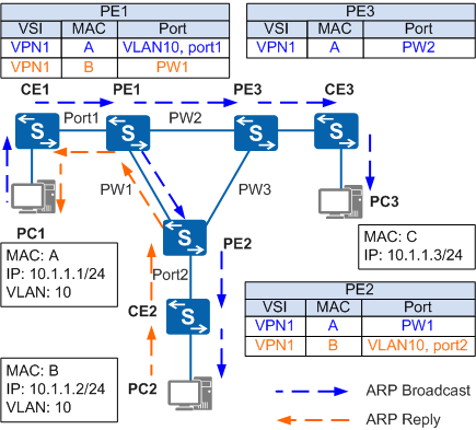
- PE1 receives the ARP Broadcast packet sent by PC1 from Port1 connected to CE1, PE1 adds the MAC address of PC1 to its own MAC address table, as shown in the blue section of the MAC entry.
- PE1 floods the ARP Broadcast packet (the blue dashed line on PE1) to other interfaces. PW1 and PW2 are regarded as interfaces in this case.
- After receiving the ARP Broadcast packet from PW1, PE2 adds the MAC address of PC1 to its own MAC address table, as shown in the blue section of the MAC entry.
- Based on split horizon, PE2 sends the ARP Broadcast packet to only the interface connecting to CE2 (as indicated by the blue dashed line), but not to PW1. This ensures that only PC2 receives the ARP Broadcast packet. VPLS split horizon ensures that packets received from public network PWs are forwarded to only private networks, not to other public network PWs.
- After PC2 receives the ARP Broadcast packet and finds that the destination address matches its own, PC2 sends an ARP Reply packet to PC1 (as indicated by the orange dashed line).
- After receiving the ARP Reply packet from PC2, PE2 adds the MAC address of PC2 to its own MAC address table, as indicated by the orange section of the MAC entry. After searching its MAC address table, PE2 sends the ARP Reply packet to PE1 over PW1.
- After receiving the ARP Reply packet from PE2, PE1 adds the MAC address of PC2 to its own MAC address table, as shown in the orange section of the MAC entry. PE1 searches its MAC address table, and sends the ARP Reply packet to PC1 through Port1.
- After receiving the ARP Reply packet from PC2, PC1 has learned the MAC address.
- While advertising the ARP Broadcast packet to PW1, PE1 also advertises the ARP Broadcast packet to PE3 over PW2. After receiving the ARP Broadcast packet, PE3 adds the MAC address of PC1 to its MAC address table, as shown in the blue section of the MAC entry. Based on split horizon, PE3 sends the ARP Broadcast packet to only PC3. Because PC3 is not the destination of the ARP Broadcast packet, PC3 does not send any ARP Reply packet.
MAC Address Withdrawal
Dynamic MAC addresses need to be updated and relearned. The VPLS draft defines a MAC Withdraw message with an optional MAC type-length-value (TLV) to remove or relearn the MAC address list.
MAC Withdraw messages enable devices to quickly delete matching MAC addresses when network topology changes. MAC Withdraw messages are classified into two types:
Messages with a MAC address list
Messages without a MAC address list
When a backup link (AC link or VC link) becomes Up, a PE that detects the link status change receives a MAC Withdraw message carrying a list of MAC addresses to be relearned. After receiving the message, the PE updates the MAC address entries in the forward information base (FIB) table of the corresponding VSI, and sends the message to PEs directly connected to it through Label Distribution Protocol (LDP) sessions. If the MAC Withdraw message contains an empty MAC address list TLV, the PE deletes all the MAC addresses in the specified VSI except the MAC address learned from the PE that sends the message.
MAC Address Aging
An aging mechanism removes no-longer needed MAC entries. If a MAC entry is not updated within the specified period of time, the entry is aged out.