HVPLS
Hierarchical Virtual Private LAN Service (HVPLS) is a technology for hierarchizing the VPLS network.
Background of HVPLS
In VPLS using BGP or LDP signaling, the basic mechanism for preventing loops is to set up a full mesh of all sites. LDP sets up fully-meshed LDP sessions among all sites, and BGP sets up fully-meshed BGP sessions among all sites. During packet forwarding, the split horizon scheme is used. Packets from a PW are therefore not forwarded to other PWs. If a VPLS network has N PEs, it has N x (N - 1)/2 connections. When the number of PEs increases, the number of VPLS connections increases by N2. For example, if the number of sites is 100, the number of LDP sessions between sites is 4950.
HVPLS can solve the problem of excessive connections and improve network scalability. HVPLS was introduced in draft-ietf-l2vpn_vpls_ldp. HVPLS hierarchizes the network into different levels. Networks at each level are fully meshed. Devices of different levels are connected through PWs and forward packets to each other. If HVPLS is used, devices do not need to comply with the split horizon scheme.
HVPLS Model
Figure 1 shows the basic HVPLS model.
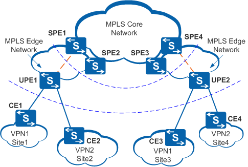
In the basic HVPLS model, PEs can be classified into the following types:
Underlayer provider edge (UPE)
A UPE is a customer convergence device directly connected to a CE. Each UPE needs to be connected to only one PE in a fully-meshed VPLS network. UPEs support routing and MPLS encapsulation. If a UPE is connected to multiple CEs and can provide the basic bridging function, frame forwarding is performed only on the UPE. This reduces the burden on the SPE.
Superstratum PE (SPE)
An SPE is a device that is connected to a UPE and is located in the core of a fully-meshed VPLS network. The SPE is connected to all devices in a fully-meshed VPLS network.
From the perspective of an SPE, UPEs function like CEs. In data forwarding, the SPE uses the PW established between itself and a UPE as an AC. The UPE adds double MPLS labels to packets sent by CEs. The outer layer is an LSP label that is switched when a packet passes through devices on the access network. The inner label is a VC label that identifies a VC. After receiving double-tagged packets, the SPE directly removes the outer label, which is a statically configured public network label. The SPE determines which VSI the SVC accesses based on the inner label.
HVPLS Access Mode
The switch supports only LDP HVPLS. In LDP HVPLS, UPEs connect to the SPE through LSPs.
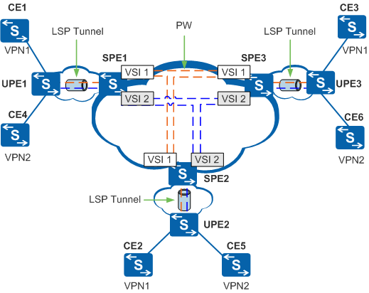
In Figure 2, UPE1 functions as a convergence device. UPE1 sets up a VC with SPE1 to access a PW. UPE1 does not set up VCs with other peers. The PW between a UPE and an SPE is called U-PW; the PW between SPEs is called S-PW.
The process of CE1 sending packets to CE 2 is as follows:
CE1 sends a packet to UPE1. The destination MAC address of the packet is CE2.
UPE1 is responsible for forwarding the packet sent by CE1 to SPE1. UPE1 adds double MPLS labels to this packet. The outer label identifies the LSP tunnel between UPE1 and SPE1; the inner label identifies the VC between UPE1 and SPE1.
The LSR between UPE1 and SPE1 transmits the packet and switches labels of the packet. The outer label is stripped at the penultimate hop.
After receiving the packet, SPE1 determines the VSI that the packet belongs to based on the MPLS inner label and finds that the packet belongs to VSI 1.
SPE1 strips the MPLS inner label added to the packet by UPE1.
SPE1 examines the entry of the VSI based on the destination MAC address of the packet, and finds that this packet needs to be sent to SPE2. SPE1 adds double MPLS labels to this packet. The outer label identifies the LSP tunnel between SPE1 and SPE2; the inner label identifies the VC between SPE1 and SPE2.
The LSR between SPE1 and SPE2 transmits the packet and switches labels of the packet. The outer label is stripped at the penultimate hop.
After receiving the packet from the S-PW side, SPE2 determines the VSI that the packet belongs to based on the MPLS inner label, and finds that the packet belongs to VSI 1. SPE2 strips the MPLS inner label added to the packet by SPE1.
SPE2 adds double MPLS labels to this packet. The outer label identifies the LSP tunnel between SPE2 and UPE2; the inner label identifies the VC between UPE2 and SPE2. SPE2 then forwards the packet.
The LSR between SPE1 and UPE2 transmits the packet and switches labels of the packet. The outer label is stripped at the penultimate hop.
After receiving the packet, UPE2 strips the MPLS inner label added to the packet by UPE2. UPE2 examines the entry of the VSI based on the destination MAC address of the packet. UPE2 finds that the packet is to be sent to CE2 and forwards the packet accordingly.
As shown in Figure 2, CE1 and CE4 access the same PE. The UPE directly forwards the packet between CE1 and CE4 without sending the packet to SPE1, because the UPE functions as a bridge. However, if CE1 sends a broadcast packet or a packet with unknown destination MAC address, UPE1 broadcasts the packet to CE4 and forwards the packet to SPE1 through the U-PW. SPE1 copies the packet and forwards it to each peer CE.
HVPLS Loop Prevention
- Full-mesh connections (full-mesh PWs) only need to be set up between SPEs, and are not required between UPEs and SPEs.
- An SPE does not forward packets received from the PW connected to the SPE to PWs that are associated with the VSI or PWs connected to other SPEs. The SPE forwards such packets to PWs connected to UPEs.
- An SPE forwards packets received from the PW connected to a UPE to all PWs that are associated with the VSI and connected to other SPEs.
HVPLS Access Link Backup
The drawback of using HVPLS is evident if only a single link exists between a UPE and an SPE or between a CE and a PE. All VPNs connected to the convergence device lose connectivity if the access link fails. Therefore, a backup link must exist for either HVPLS access model. Normally, each device uses only a single link (the master link) for access. If the VPLS system detects that the access link has failed, the system starts using the backup link to ensure the continuity of the VPN service.
For HVPLS in LSP access mode, an LDP session is run between a UPE and an SPE. You can determine whether the master PW has failed based on the status of the LDP session.
In Figure 3, PW4 is the master PW between UPE1 and SPE1. After UPE1 detects that PW4 has failed, it automatically starts using the backup route for PW4 to transmit packets.
A packet with the MAC address as 0001-1111-abcd reaches CE3 through PW4. Using the VPLS MAC address learning mechanism of VPLS, SPE1 and SPE3 learn the MAC address of the corresponding virtual interface (as shown in blue in the MAC address table). SPE3 preserves the MAC address entry because the link switchover of the peer is unknown.
The packet from CE3 cannot be forwarded to CE1 based on the original entry in the MAC address table. When performing the switchover between the master PW and backup PW, UPE therefore needs to withdraw the related MAC address. The MAC address can be withdrawn by sending an LDP MAC Withdraw message.
If multiple MAC addresses need to be withdrawn, you can directly send a MAC Withdraw message with the MAC address list as null. This clears all MAC addresses on the VPN except the entry of the link that sends the MAC Withdraw message.
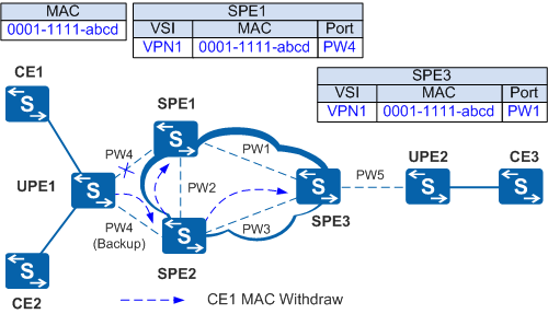
The procedure for sending and processing the MAC Withdraw message is as follows:
UPE1 sends a MAC Withdraw message (shown by the dashed blue line) to SPE2.
SPE2 processes the MAC Withdraw message and learns the MAC address of the backup route for PW4. The MAC address is 0001-1111-abcd.
SPE2 sends the MAC Withdraw message to the peers SPE1 and SPE3. SPE1 and SPE3 process the MAC Withdraw message and learn the MAC address 0001-1111-abcd.