VRRP Redundancy
VRRP redundancy is the basic VRRP working mode. As shown in Figure 1, in VRRP redundancy mode, a virtual router consists of one master and multiple backups.
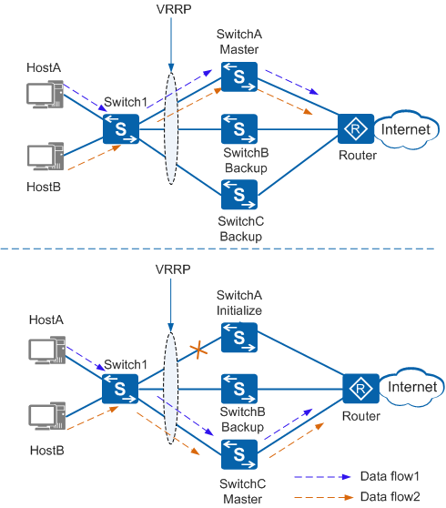
In normal cases, SwitchA is the master and forwards traffic. SwitchB and SwitchC are backups and do not forward traffic. SwitchA periodically sends VRRP Advertisement packets to SwitchB and SwitchC, notifying them that the master is working properly. If SwitchA is faulty, either SwitchB or SwitchC is selected as the new master, depending on their priorities. The new master then takes over traffic forwarding.
After SwitchA recovers, it becomes the master if preemption mode is enabled or remains in Backup state if non-preemption mode is enabled.
The following describes the configuration of the three switches on the network shown in Figure 1:
- SwitchA is the master, with the priority 120. It uses the delayed preemption mode.
- SwitchB is the backup, with the priority 100. It uses the immediate preemption mode.
- SwitchC is the backup, with the priority 110. It uses the immediate preemption mode.
The following describes how traffic is forwarded on the network:
- When SwitchA is running properly, traffic sent from users is transmitted along the path Switch1 -> SwitchA -> Router. SwitchA periodically sends VRRP Advertisement packets to SwitchB and SwitchC, notifying them that the master is working properly.
- When a fault occurs on SwitchA, VRRP does not function on SwitchA, which stops sending VRRP Advertisement packets to SwitchB and SwitchC. Because SwitchC has a higher priority than SwitchB, SwitchC becomes the master. SwitchC starts to send VRRP Advertisement packets and gratuitous ARP packets, whereas SwitchB remains in Backup state. User traffic is transmitted along the path Switch1 -> SwitchC -> Router.
- When SwitchA recovers, its priority is restored to 120 and it enters the Backup state. SwitchC continues sending VRRP Advertisement packets. When SwitchA receives a VRRP Advertisement packet, it compares the priority in the packet with its own priority and detects that its priority is higher. After the preemption delay, SwitchA reverts to being the master and starts to send VRRP Advertisement packets and gratuitous ARP packets. User traffic is again transmitted along the path Switch1 -> SwitchA -> Router.