Agile Distributed SFN Roaming
Overview
In healthcare scenarios, handheld healthcare terminals do not comply with the 802.11k, 802.11v, or 802.11r protocol. Therefore, roaming aggressiveness is poor during the services such as ward round, infusion check, and vital sign recording. This may easily cause a high packet loss ratio and long delay. Users will have to re-log in to the application software or scan the terminal code. The network access service is interrupted, greatly affecting working efficiency of doctors and nurses.
To address these issues, Huawei launches the agile distributed SFN roaming function. (SFN is short for same-frequency network.) On an agile distributed WLAN network, all RUs associated with a central AP are deployed on the same channel and communicate with STAs using the public BSSID. Within the coverage of the SSID signal, freely moving STAs do not perceive roaming, and services are not interrupted during the roaming.
Compared with traditional intra-central AP roaming, agile distributed SFN roaming eliminates the impact of STA differences on the roaming effect. Additionally, this roaming mode is smooth and fast, and significantly reduces the packet loss ratio, without the user reassociation, authentication, and key negotiation processes.
Implementation
Figure 1 shows the implementation of agile distributed SFN roaming.
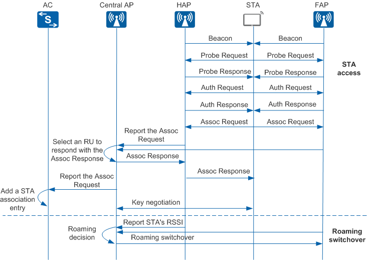
Two phases are involved:
STA access
- All RUs broadcast Beacon frames to STAs using the public BSSID automatically generated by the central AP based on the MAC address.
- A STA sends a Probe Request frame. After receiving the Probe Request frame, all RUs respond with a Probe Response frame using the public BSSID.
- The STA sends an Auth Request frame. After receiving the Auth Request frame, all RUs respond with an Auth Response frame using the public BSSID.
- The STA sends an Assoc Request frame. After receiving the Assoc Request frame, all RUs forward it to the central AP and notifies the central AP of the STA's signal-to-noise ratio (SNR).
- The central AP selects an RU with the optimal SNR to respond to the STA with an Assoc Response. Within a specified period, the central AP discards Assoc Request frames reported by other RUs. Subsequently, only the selected RU communicates with the STA.
- The central AP reports the Assoc Request frame of the STA to the AC. Then the AC adds STA information to the STA association table.
- The central AP, RU, and STA perform unicast and multicast key negotiation.
Roaming switchover
- The HAP (RU with which the STA first associates) periodically reports the STA RSSI to the central AP. The FAP (RU to which the STA roams) periodically reports the RSSI of neighbors to the central AP.
- The central AP selects the optimal RU as the FAP using the roaming
decision algorithm, and synchronizes STA information to the FAP. The
central AP checks the following switchover conditions in sequence.
If any of the conditions is met, a roaming switchover occurs. If multiple
RUs meet the following three conditions, the RU with the highest RSSI
is selected for the roaming switchover.
- The cumulative RSSI change value of the STA reaches the specified threshold.
- The number of times the RSSI of surrounding RUs is higher than that of the local RU reaches the specified value.
- The RSSI gap between the local RU and surrounding RUs reaches the specified value.
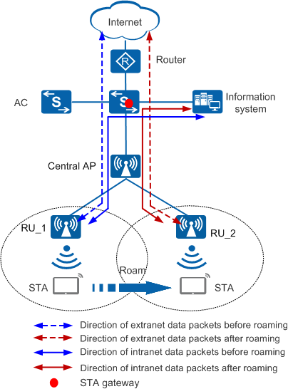
Packet Processing
The following assumes that service data packets are forwarded in direct mode. Figure 2 shows how intranet and extranet data packets for agile distributed SFN roaming are processed. In tunnel forwarding mode, intranet and extranet data packets are forwarded between the central AP and RUs in the same way as that in direct forwarding mode.
| Before Roaming | After Roaming |
|---|---|
|
|
| Before Roaming | After Roaming |
|---|---|
|
|