Radio Calibration
Overview
On a WLAN, the operating status of APs is affected by the radio environment. For example, adjacent APs using the same working channel interfere with each other, and a large-power AP can interfere with adjacent APs if they work on overlapping channels. Radio calibration can dynamically adjust channels and power of APs managed by the same AC to ensure that the APs work in a way that optimizes performance.
Channel Adjustment
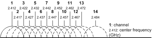
On a WLAN, adjacent APs must work on non-overlapping channels to avoid radio interference. For example, the 2.4 GHz frequency band is divided into 14 overlapping 20 MHz channels, as shown in Figure 1.

Enterprise technical support website: https://support.huawei.com/enterprise
Carrier technical support website: https://support.huawei.com
The 5 GHz frequency band has richer spectrum resources. In addition to 20 MHz channels, APs working on the 5 GHz frequency band support 40 MHz, 80 MHz, and larger-bandwidth channels, as shown in Figure 2.

- Two neighboring 20 MHz channels are bonded into a 40 MHz channel. One of the two 20 MHz channels is the primary channel, and the other the auxiliary channel.
- Two neighboring 40 MHz channels are bonded into an 80 MHz channel. In an 80 MHz channel, one 20 MHz channel is selected as the primary channel. The other 20 MHz channel making up the 40 MHz channel with the primary channel is called the auxiliary 20 MHz channel. The 40 MHz channel not containing the primary channel is called the auxiliary 40 MHz channel.
- Two neighboring 80 MHz channels are bonded into a 160 MHz channel. In a 160 MHz channel, one 20 MHz channel is selected as the primary channel. The other 20 MHz channels making up the 80 MHz channel with the primary channel are called the auxiliary 20 MHz channels. The 40 MHz channels not containing the primary channel are called the auxiliary 40 MHz channels. The 80 MHz channel not containing the primary channel is called the auxiliary 80 MHz channel. At most two 160 MHz channels are supported on the 5 GHz frequency band.
- Two non-neighboring 80 MHz channels are bonded into an 80+80 MHz channel. The division of primary and auxiliary channels is similar to that for a 160 MHz channel. Compared to the 160 MHz channel, the 80+80 MHz channel allows for more than three non-overlapping channels on the 5 GHz frequency band, which can be used for cellular channel planning and meet wireless network deployment requirements.
Figure 3 shows the channel bonding.
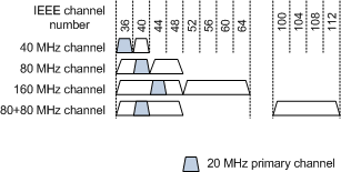
The primary channel is used for transmission of the management and control packets. A channel is idle only when its primary channel is idle.
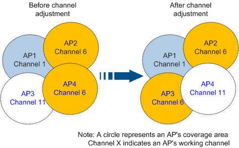
Figure 4 shows an example of channel distribution before and after channel adjustment. Before channel adjustment, both AP2 and AP4 use channel 6. After channel adjustment, AP4 uses channel 11 so that it does not interfere with AP2.
After channel adjustment, each AP is allocated an optimal channel to minimize or avoid adjacent-channel or co-channel interference, ensuring reliable data transmission on the network.
In addition to optimizing radio performance, channel adjustment can also be used for dynamic frequency selection (DFS). In some regions, radar systems work in the 5 GHz frequency band, which can interfere with radio signals of APs working in the 5 GHz frequency band. The DFS function enables APs to automatically switch to other channels when they detect interference on their current working channels.
During the DFS process, radar signals may be incorrectly determined. If radar signals are detected occasionally on a single AP, it may be a mistake. If radar signals are detected for multiple times on an AP or simultaneously on multiple APs, the radar signals may be determined. Then the APs can process the signals accordingly. To minimize mis-detections, all Huawei AP models are optimized for DFS mis-detections to distinguish radar signals and non-radar signals more accurately.
Power Adjustment
An AP's transmit power determines its radio coverage area. APs with higher power have larger coverage areas. A traditional method to control the radio power is to set the transmit power to the maximum value to maximize the radio coverage area. However, a high transmit power may cause interference with other wireless devices. Therefore, an optimal power is required to balance the coverage area and signal quality.
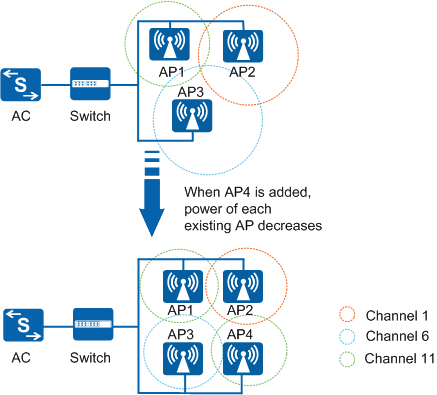
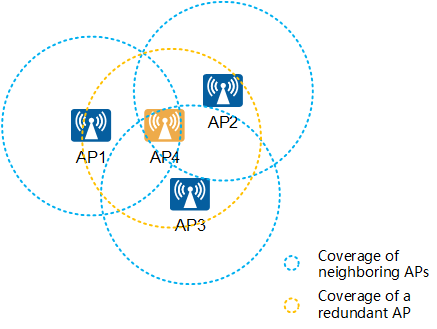
- When an AP is added to the network, the transmit power of neighboring APs decreases, as shown in Figure 5. The area of the circle around an AP represents the AP's coverage area after transmit power adjustment. When AP4 is added to the network, the transmit power of each AP decreases automatically.
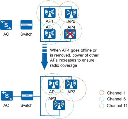
- When an AP goes offline or fails, power of neighboring APs increases, as shown in Figure 6.
Redundant Radio Adjustment
- Switched to 5G: If many 5 GHz channel resources are available, a redundant radio is switched to the 5 GHz mode, increasing the maximum capacity of 5 GHz radios.
- Switched to monitor: If no more 5 GHz channel resources are available, a redundant radio is switched to the monitor mode and used for scanning services.
- Disabled: Disabling a redundant radio decreases co-channel interference but does not affect coverage.
Manually identifying, switching, or disabling redundant radios will greatly increase network maintenance costs. To resolve this issue, Dynamic Frequency Assignment (DFA) is adopted to automatically identify, switch, or disable redundant radios, reducing 2.4 GHz co-channel interference and increasing system capacity.
Implementation
- AP: actively or passively collects radio environment information and sends the information to the AC. The AC then delivers the calibration results.
- AC: maintains the AP neighbor topology based on radio environment information received from the AP, uses calibration algorithms to allocate AP channels and transmit power, sends calibration results to APs.
ACs support global radio calibration and partial radio calibration:
- Global radio calibration:
Global radio calibration takes effect on all APs managed by an AC. The AC controls channels and transmit power of all APs in the region to achieve best radio performance. Generally, this calibration mode is used on a newly deployed WLAN or a WLAN with a few services.
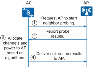
The Figure 8 shows the global radio calibration process.The global radio calibration process is as follows:- After global radio calibration is enabled, the AC sends a notification to each AP, requesting the AP to start neighbor probing.
- The APs periodically implement neighbor probing and report neighbor information to the AC.
After the AC receives probe results from all of the APs, it uses a global radio calibration algorithm to allocate channels, bandwidth, and power to the APs.
Global radio calibration algorithms include the Dynamic Channel Allocation (DCA), Dynamic Bandwidth Selection (DBS), Dynamic Bandwidth Selection (DBS), DFA, and Transmit Power Control (TPC) algorithms.
- The AC delivers calibration results to the APs. After the AC implements global radio calibration for the first time, the AC starts the next global radio calibration until it receives neighboring information of all APs. The AC continuously implements global radio calibration in order to obtain the optimal and accurate calibration results.
Neighbor probe
Two neighbor probe modes are available.Active probe: The AP actively sends Probe Request frames to notify surrounding APs of its existence. Active probe is used to establish neighbor relationships and obtain the maximum interference signal strength.
The active probe process is as follows: An AP periodically sends Probe Request frames destined for a specified multicast address on different channels. After receiving the frames, surrounding APs learn that the AP is a neighbor and collects information about the AP, in which the Received Signal Strength Indicator (RSSI) is the key factor.
Passive probe: The AP receives neighbor information to detect neighboring APs. The passive probe is used to collect interference information from neighboring APs and rogue APs.
Global calibration algorithm
The global calibration algorithm achieves global optimization through partial optimizations. Global calibration is implemented through AP channel and power adjustment. Instead of being coupled to each other, the algorithms for channel adjustment (DCA) and power adjustment (TPC) are independent of each other.
DCA algorithm
Global calibration divides all APs into several calibration groups based on the relationships between the APs and allocates channels to each group. In each radio calibration group, simple exhaustion and iteration algorithms are used to list all possible AP-Channel combinations and choose the optimal combination.
DBS algorithm
For 5 GHz Wi-Fi networks in non-high-density indoor scenarios (AP spacing: 10 m to 15 m), the DBS algorithm can automatically identify the service priority, throughput, and interference, and switch the channel and bandwidth accordingly, improving network throughput and ensuring quality of core services. The algorithm takes effect in the following ways:
- Group available 5 GHz channels based on the capability of forming 80 MHz or 40 MHz channels.
- Sort APs based on the topology distance.
- Allocate the main channel to STAs based on factors including the interference factor, bandwidth satisfaction degree, channel isolation degree, and channel reuse factor.
- Bond 20 MHz channels of APs into 40 MHz or 80 MHz in the specified sequence.
DFA algorithm
The DFA algorithm is used to automatically identify and adjust redundant radios. DFA process a redundant radio as follows:- After identifying a radio as a redundant radio, the DCA algorithm switched the radio to the 5 GHz or monitor mode based on the channel, bandwidth, and interference of other radios on the network.
- After the redundant radio is switched to the 5 GHz mode, it works on the default 5 GHz channel. In this case, the DCA algorithm is used again to adjust the radio channel.
- During this process, if a coverage hole is detected on 2.4 GHz radios, the 5 GHz radio is switched back to the 2.4 GHz mode.
- If the AC restarts, APs go online again with the previous configurations including the channel, power, frequency band, and radio status. If an AP goes online after a long period of time, the AC determines redundant radios and allocates the band to radios again.
- When the DFA function is disabled, the redundant radio configuration is restored. For example, the radio in 5 GHz or monitor mode will be restored to the 2.4 GHz.
- TPC algorithmThe TPC algorithm aims to choose the proper transmit power which can meet coverage requirements, without causing large interference to neighboring APs. The TPC algorithm works in the following ways:
The algorithm estimates the deployment density of APs based on the number of AP neighbors, and determines the initial transmit power, lower and upper interference thresholds.
The level of interference specified by the lower interference threshold is low, and within the allowed range. In this case, two neighboring APs cannot detect interference from each other and can send packets simultaneously.
The level of interference specified by the upper interference threshold is large. In this case, two neighboring APs can easily detect the interference and must compete to send packets through CSMA.
- The algorithm re-detects RSSIs of neighbors. If the interference caused by the neighbor is smaller than the lower interference threshold, the algorithm determines whether to raise transmit power according to their difference. If the interference caused by the neighbor is greater than the upper interference threshold, the algorithm determines whether to reduce transmit power according to their difference.
- Partial radio calibration
Partial radio calibration aims to adjust working channels and power of some APs to optimize the radio environment if it deteriorates in only some areas. Similar to the global radio calibration, the partial radio calibration uses DCA and TPC algorithms. Partial radio calibration is triggered in the following scenarios:
- An AP goes online: When detecting that an AP goes online, the AC allocates a working channel and power to the new AP. To achieve the optimal performance, the AC may re-allocate the working channels and transmit power of neighboring APs. For example, to prevent interference between the new AP and its neighbors, the AC will reduce the transmit power of the AP neighbors.
- An AP goes offline: When detecting that an AP goes offline, the AC executes the calibration algorithm to increase the transmit power of neighboring APs to eliminate coverage holes. An AP may be restarted unexpectedly or manually restarted for temporary maintenance. In this situation, the AC does not start the calibration algorithm immediately. Instead, the AC starts radio calibration only after the neighbor information is updated.
- Interference from a rogue AP is detected: If a rogue AP is identified through neighbor probes, interference information is collected and used for radio calibration. If the interference value exceeds the threshold (-65 dBm by default), the interference is considered serious, and partial radio calibration is triggered. The device adjusts working channels of neighboring APs to avoid interference from the rogue AP.
- The radio environment deteriorates: Radio environment deteriorates due to an increase in lost packets and error codes caused by interference or weak signals. In scenario, partial radio calibration may be triggered if it can improve the radio environment. If the AP finds that the channel utilization or noise floor is high, or cannot send Beacon frames, the AP reports the issue to the AC to trigger partial radio calibration.
- Interference from non-Wi-Fi devices is detected: Non-Wi-Fi devices, including microwave ovens and cordless phones, work on the same frequency as the APs, and may cause interference. If the spectrum analysis module identifies interference from non-Wi-Fi devices. If the interference is serious or large interference occurs multiple times in a specified period, the module triggers partial radio calibration and adjusts AP channels and power to avoid interference.
- Partial radio calibration is manually triggered: You can trigger partial radio calibration based on the AP or AP group.
Big Data Calibration
It is recommended that radio calibration be enabled during off-peak hours at night to prevent impact on services. If the radio environment of an AP differs significantly during off-peak hours and peak hours, the radio calibration effect during off-peak hours may be inapplicable to service requirements during peak hours. With the Big Data calibration function, the Big Data analyzer (CampusInsight) analyzes KPI information collected by APs on the whole day and provides prediction data. In this manner, the radio calibration result during off-peak hours better meets service needs during peak hours.
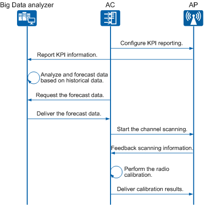
As shown in Figure 9, an AP reports KPI information to the Big Data analyzer through the KPI information report function. The Big Data analyzer then summarizes, analyzes, and predicts the KPI information. When scheduled radio calibration is triggered next time, the device performs radio calibration based on the real-time channel quality and the prediction data provided by the Big Data analyzer. The radio calibration result can help avoid non-continuous interference sources and better meet service requirements.
In densely populated scenarios such as canteens, offices, waiting rooms, and cafes, a large number of STAs connect to APs and then leave after a short period of time. The air interface resources of these APs are occupied by these STAs, resulting in performance deterioration. In addition, the network access experience of such STAs is affected due to unnecessary switching of network access modes. For ease of description, these APs are called edge APs, and STAs that are temporarily connected and quickly leave are called nomadic STAs. The Big Data analyzer can determine whether an AP is an edge AP based on the network indicator data reported by the AP. In the next Big Data calibration, the Big Data analyzer adjusts the AP's transmit power to suppress access of nomadic STAs and improve the health of AP radios.