BGP VPN Route Crossing
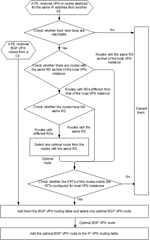
Remote route crossing: After a PE receives a BGP VPNv4 route from a remote PE, the local PE matches the export target (ERT) of the route against the import targets (IRTs) configured for local VPN instances. If the ERT matches the IRT of a local VPN instance, the PE converts the BGP VPNv4 route to a BGP VPN route and adds the BGP VPN route to the routing table of this local VPN instance.
Local route crossing: A PE matches the ERT of a BGP VPN route in a local VPN instance against the IRTs configured for other local VPN instances. If the ERT matches the IRT of a local VPN instance, the PE adds the BGP VPN route to the routing table of this local VPN instance. Locally crossed routes include both locally imported routes and routes learned from VPN peers.
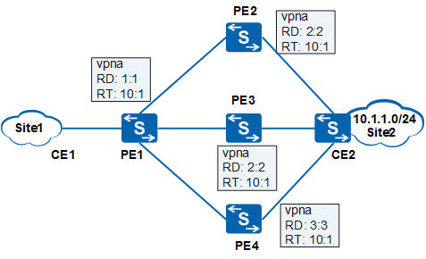
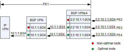
After receiving the BGP VPNv4 routes from PE2, PE3, and PE4, PE1 adds them to the BGP VPNv4 routing table.
The RDs configured for the VPN instance on PE2 and PE3 are the same. Therefore, the BGP VPNv4 routes that PE2 and PE3 send to PE1 are the same. On receipt of the BGP VPNv4 routes from PE2 and PE3, PE1 selects an optimal BGP VPNv4 route (the route from PE3 in this example) from them, converts the optimal BGP VPNv4 route and the BGP VPNv4 route received from PE4 to BGP VPN routes by removing their RDs, and adds the BGP VPN routes to the routing table of the BGP VPN instance.
PE1 selects an optimal BGP VPN route from the two BGP VPN routes based on BGP route selection policies and adds the optimal BGP VPN route to the IP VPN instance routing table.

If a PE receives two BGP VPNv4 routes with the same RD from remote PEs, only one of the BGP VPNv4 routes can be added to the routing table of the BGP VPN instance. As a result, VPN FRR or load balancing cannot be implemented between VPN routes.