IPv6 over IPv4 Tunnel
Tunneling is an encapsulation technology that encapsulates packets of a network layer protocol as packets of another one. A tunnel is a virtual point-to-point (P2P) connection. It provides a path through which encapsulated packets are transmitted. Datagrams are encapsulated at one end, and decapsulated at the other end of the tunnel. Tunneling technology refers to the process that datagrams are encapsulated, transmitted, and decapsulated and is significant for the transition from IPv4 to IPv6.
Exhaustion of IPv4 addresses brings an urgent demand for the transition to IPv6. As IPv6 is not compatible with IPv4, devices will need replacing on the original IPv4 network. Replacing a large number of devices on the IPv4 network however costs a significant amount and will cause service interruption to the current network. Therefore, transition from IPv4 networks to IPv6 networks must happen gradually. During the early stage of transition, a large number of IPv4 networks have been deployed, whereas IPv6 networks remain as isolated sites over the world. You can create tunnels on the IPv4 networks to connect to IPv6 isolated sites. These tunnels are called IPv6 over IPv4 tunnels.
Figure 1 shows how to apply the IPv6 over IPv4 tunnel.
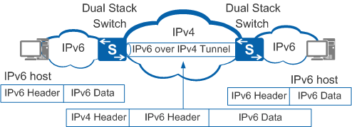
On the border device, the IPv4/IPv6 dual protocol stack is enabled, and an IPv6 over IPv4 tunnel is configured.
After the border device receives a packet from the IPv6 network, the device appends an IPv4 header to the IPv6 packet to encapsulate the IPv6 packet as an IPv4 packet if the destination address of the IPv6 packet is not the device and the outbound interface of the next hop is the tunnel interface.
On the IPv4 network, the encapsulated packet is transmitted to the remote border device.
The remote border device decapsulates the packet, removes the IPv4 header, and sends the decapsulated IPv6 packet to the IPv6 network.
- Manual tunnel: If a tunnel is created manually, a border router cannot automatically obtain an IPv4 address at the end point. You must manually configure an end point IPv4 address before packets can be transmitted to the remote border router.
- Automatic tunnel: If a tunnel is created automatically, a border router can automatically obtain an IPv4 address at the end point. The addresses of two interfaces on both ends of the tunnel are IPv6 addresses with IPv4 addresses embedded. The border router extracts IPv4 addresses from destination IPv6 addresses.
Manual Tunnel
Based on encapsulation modes of IPv6 packets, manual tunnels classify into IPv6 over IPv4 manual tunnels or IPv6 over IPv4 Generic Routing Encapsulation (GRE) tunnels.
IPv6 over IPv4 Manual Tunnel
The border router uses the received IPv6 packet as the payload and encapsulates the IPv6 packet as an IPv4 packet. You must manually specify the source and destination addresses of a manual tunnel. A manual tunnel is created between two border routers to connect IPv4 isolated IPv6 sites, or created between a border router and a host to enable the host to access an IPv6 network. Hosts and border routers on both ends of a manual tunnel must support the IPv4/IPv6 dual protocol stack. Other devices only need to support a single protocol stack. If you create multiple IPv6 over IPv4 manual tunnels between one border router and multiple hosts, the configuration workload is heavy. Therefore, an IPv6 over IPv4 manual tunnel is commonly created between two border routers to connect IPv6 networks.
Figure 2 shows the encapsulation format of an IPv6 over IPv4 packet.

The forwarding mechanism of an IPv6 over IPv4 manual tunnel is as follows: After a border router receives a packet from the IPv6 network, it searches the destination address of the IPv6 packet in the routing and forwarding table. If the packet is forwarded from a virtual tunnel interface, the router encapsulates the packet based on the source and destination IPv4 addresses configured on the interface. The IPv6 packet is encapsulated as an IPv4 packet and processed by the IPv4 protocol stack. The encapsulated packet is forwarded through the IPv4 network to the remote end of the tunnel. After the border router on the remote end of the tunnel receives the encapsulated packet, it decapsulates the packet and processes the packet using the IPv6 protocol stack.
IPv6 over IPv4 GRE Tunnel
An IPv6 over IPv4 GRE tunnel uses the standard GRE tunneling technology to provide P2P connections. You must manually specify addresses for both ends of the tunnel. Any types of protocol packets that GRE supports can be encapsulated and transmitted through a GRE tunnel. The protocols may include IPv4, IPv6, Open Systems Interconnection (OSI), and Multiprotocol Label Switching (MPLS).
Figure 3 shows the encapsulation and transmission process on an IPv6 over IPv4 GRE tunnel.
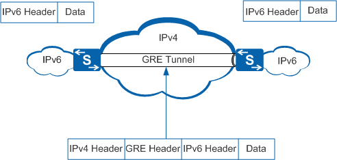
The forwarding mechanism of an IPv6 over IPv4 GRE tunnel is the same as that of an IPv6 over IPv4 manual tunnel. For details, see GRE Configuration in the S2720, S5700, and S6700 V200R019C10 Configuration Guide - VPN.
Automatic Tunnel
You only need to configure the start point of an automatic tunnel, and the device automatically obtains the end point of the tunnel. The tunnel interface uses a special form of IPv6 address with an IPv4 address embedded. The device obtains the IPv4 address from the destination IPv6 address and uses the IPv4 address as the end point address of the tunnel.
Based on the encapsulation modes of IPv6 packets, automatic tunnels are classified into IPv6-to-IPv4 tunnels, and Intra-Site Automatic Tunnel Addressing Protocol (ISATAP) tunnels.
IPv6-to-IPv4 Tunnel
An IPv6-to-IPv4 tunnel also uses an IPv4 address that is embedded in an IPv6 address. Unlike IPv4-compatible IPv6 tunnels, you can create IPv6-to-IPv4 tunnels between two routers, a router and a host, and two hosts. An IPv6-to-IPv4 address uses the IPv4 address as the network ID. Figure 4 shows the format of an IPv6-to-IPv4 address.

- FP: format prefix of a global unicast address. The value is 001.
- TLA ID: top level aggregation identifier. The value is 0x0002.
- SLA ID: site level aggregation identifier.
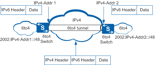
An IPv6-to-IPv4 address is expressed in the format of 2002::/16. An IPv6-to-IPv4 network is expressed as 2002:IPv4 address::/48. An IPv6-to-IPv4 address has a 64-bit prefix composed of a 48-bit 2002:IPv4 address and a 16-bit SLA. A 2002:IPv4 address in the format of 2002:a.b.c.d is determined by the IPv4 address allocated to the router and the SLA is defined by the user. Figure 5 shows the encapsulation and forwarding process of the IPv6-to-IPv4 tunnel.
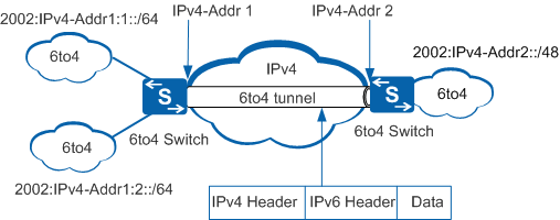
One IPv4 address can be used as the source address of only one IPv6-to-IPv4 tunnel. When a border device connects to multiple IPv6-to-IPv4 networks using the same IPv4 address as the source address of the tunnel, the IPv6-to-IPv4 networks share a tunnel and are identified by SLA ID in the IPv6-to-IPv4 address. Figure 6 details this configuration.
ISATAP Tunnel
ISATAP is another automatic tunneling technology. The ISATAP tunnel uses a specially formatted IPv6 address with an IPv4 address embedded into it. Different from the IPv6-to-IPv4 address that uses the IPv4 address as the network prefix, the ISATAP address uses the IPv4 address as the interface ID. Figure 7 shows the format of the interface ID of an ISATAP address.
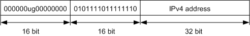
The "u" bit in the IPv4 address that is globally unique is set to 1. Otherwise, the "u" bit is set to 0. "g" is the individual/group bit. An ISATAP address contains an interface ID and it can be a global unicast address, link-local address, ULA address, or multicast address. The device obtains the first 64 bits of an ISATAP address by sending Request packets to the ISATAP router. Devices on both ends of the ISATAP tunnel run the Neighbor Discovery (ND) protocol. The ISATAP tunnel considers the IPv4 network as a non-broadcast multiple access (NBMA) network.
ISATAP allows IPv6 networks to be deployed within existing IPv4 networks, which is simple and makes networks easily expandable. ISATAP is suitable for transitions of local sites and supports local routing within IPv6 sites, global IPv6 routing domains, and automatic IPv6 tunnels. ISATAP can be used together with NAT to allow the use of an IPv4 address that is not globally unique within the site. Typically, an ISATAP tunnel is used within the site, and does not require a globally unique IPv4 address embedded.
Figure 8 shows a typical application of the ISATAP tunnel.
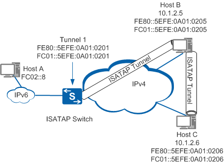
In Figure 8, Host B and Host C are located on an IPv4 network. They both support dual protocol stacks and have private IPv4 addresses. You can perform the following operations to enable the ISATAP function on Host B and Host C:
- Configure an ISATAP tunnel interface to generate an interface ID based on the IPv4 address.
- Encapsulate a link-local IPv6 address based on the interface ID. When a host obtains the link-local IPv6 address, it can access the IPv6 network on the local link.
- The host automatically obtains a global unicast IPv6 address and ULA address.
- The host obtains an IPv4 address from the next hop IPv6 address as the destination address, and forwards packets through the tunnel interface to communicate with another IPv6 host. When the destination host is located on the same site as the source host, the next hop address is the address of the source host. When the destination host is not located on the local site, the next hop address is the address of the ISATAP device.
6PE
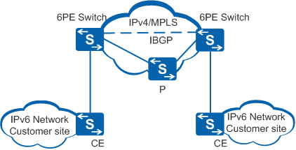
IPv6 Provider Edge (6PE) is a transition technology from the IPv4 to the IPv6 network. With 6PE devices, Independent Service Providers (ISPs) can provide cost-effective access services for isolated IPv6 network users over the existing IPv4 backbone network. The 6PE device labels IPv6 routing information and floods the information onto the ISP's IPv4 backbone network through Internal Border Gateway Protocol (IBGP) sessions. The IPv6 packets are labeled before flowing into either GRE tunnels or MPLS LSPs on the backbone network. To allow IPv6 packet exchange on IPv4/MPLS networks through MPLS, LSPs can simply update the PE devices. Therefore, 6PE technology is a cost-effective solution to IPv4-to-IPv6 transition.
Figure 9 shows the typical 6PE networking diagram.
For more details about 6PE, see S2720, S5700, and S6700 V200R019C10 Configuration Guide - MPLS.