Basic Concepts of IS-IS
IS-IS Topology Structure
Overall IS-IS Topology
IS-IS uses a two-level hierarchy (backbone area and non-backbone area) to support large-scale routing networks. Generally, Level-1 routers are deployed in non-backbone areas, whereas Level-2 and Level-1-2 routers are deployed in backbone areas. Each non-backbone area connects to the backbone area through a Level-1-2 router.
Figure 1 shows a network that runs IS-IS. The network is similar to an OSPF network topology with multiple areas. The backbone area contains all the routers in Area 1 and Level-1-2 routers in other areas.
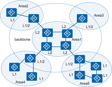
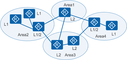
Figure 2 shows another type of IS-IS topology. In this topology, Level-2 routers belong to different areas. All the physically contiguous Level-1-2 and Level-2 routers form the backbone area of IS-IS.
- In IS-IS, each router belongs to only one area. In OSPF, different interfaces of a router may belong to different areas.
- In IS-IS, no area is defined as the backbone area. In OSPF, Area 0 is defined as the backbone area.
- In IS-IS, Level-1 and Level-2 routes are calculated using the SPF algorithm to generate the shortest path tree (SPT). In OSPF, the SPF algorithm is used only in the same area, and inter-area routes are forwarded by the backbone area.
IS-IS Router Types
Level-1 router
A Level-1 router manages intra-area routing. It establishes neighbor relationships with only the Level-1 and Level-1-2 routers in the same area and maintains a Level-1 link state database (LSDB). The LSDB contains intra-area routing information. A packet to a destination outside this area is forwarded to the nearest Level-1-2 router.
Level-2 router
A Level-2 router manages inter-area routing. It can establish neighbor relationships with Level-2 or Level-1-2 routers in different areas and maintains a Level-2 LSDB. The LSDB contains inter-area routing information.
All Level-2 routers form the backbone network of the routing domain. They establish Level-2 neighbor relationships and are responsible for inter-area communication. Level-2 routers in the routing domain must be physically contiguous to ensure the continuity of the backbone network. Only Level-2 routers can exchange data packets or routing information with routers outside the routing domain.
Level-1-2 router
A router that belongs to both a Level-1 area and a Level-2 area is called a Level-1-2 router. It can establish Level-1 neighbor relationships with Level-1 and Level-1-2 routers in the same area. It can also establish Level-2 neighbor relationships with Level-2 and Level-1-2 routers in different areas. A Level-1 router must be connected to other areas through a Level-1-2 router.
A Level-1-2 router maintains two LSDBs: a Level-1 LSDB and a Level-2 LSDB. The Level-1 LSDB saves for intra-area routing and the Level-2 LSDB saves for inter-area routing.
IS-IS Network Types
IS-IS supports only two types of networks. In terms of physical links, IS-IS networks can be classified into the following link types:
- Broadcast: such as Ethernet and Token-Ring
- Point-to-point: such as PPP and HDLC

IS-IS cannot run on Point to MultiPoint (P2MP) networks.
DIS and Pseudonode
In a broadcast network, IS-IS needs to elect a Designated Intermediate System (DIS) from all the routers. DISs are used to create and update pseudonodes and generate link state protocol data units (LSPs) of pseudonodes to describe available network devices.
The pseudonode is used to simulate a virtual node in the broadcast network and is not an actual router. In IS-IS, a pseudonode is identified by the system ID of the DIS and the 1-byte Circuit ID (its value is not 0).
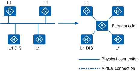
As shown in Figure 3, the use of pseudonodes simplifies the network topology and shortens LSPs. When the network changes, the number of generated LSPs is reduced, and the SPF consumes fewer resources.
Level-1 and Level-2 DISs are elected separately. You can configure different priorities for DISs of different levels. The router with the highest priority is elected as the DIS. If there are multiple routers with the same highest priority on a broadcast network, the one with the highest MAC address is chosen. The DISs of different levels can be the same router or different routers.
On an IS-IS broadcast network, the router with priority 0 also takes part in DIS election. In OSPF, the router with priority 0 does not take part in DR election.
In IS-IS, when a new router that meets the requirements of being a DIS connects to a broadcast network, the router is elected as the new DIS, and the previous pseudonode is deleted. This causes a new flooding of LSPs. In OSPF, when a new router connects to a network, it is not immediately elected as the DR even if it has the highest DR priority.
On an IS-IS broadcast network, routers (including non-DIS routers) of the same level on a network segment set up adjacencies. In OSPF, routers set up adjacencies with only the DR and backup designated router (BDR).
On an IS-IS broadcast network, although all the routers set up adjacencies with each other, the LSDBs are synchronized by the DISs.
IS-IS Address Structure
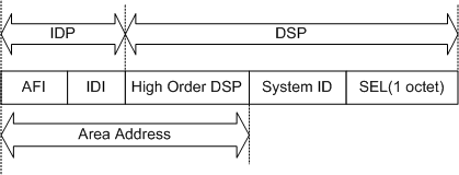
- The IDP is similar to the network ID in an IP address. It is defined by the ISO and consists of the authority and format identifier (AFI) and the initial domain identifier (IDI). The AFI indicates the address allocation authority and address format, and the IDI identifies a domain.
- The DSP is similar to the subnet ID and host address in an IP address. The DSP consists of the High Order DSP (HODSP), system ID, and NSAP Selector (SEL). The HODSP is used to divide areas, the system ID identifies a host, and the SEL indicates the service type.
Area Address
The IDP and the HODSP of the DSP identify a routing domain and the areas in a routing domain. Therefore, the combination of the IDP and HODSP is called an area address, which is similar to an area number in OSPF. The area addresses of routers in the same Level-1 area must be the same, while the area addresses of routers in the Level-2 area can be different.
In general, a router can be configured with only one area address. The area address of all nodes in an area must be the same. In the implementation of a device, an IS-IS process can be configured with a maximum of three area addresses to support seamless combination, division, and transformation of areas.
System ID
A system ID uniquely identifies a host or a router in an area. In the device, the fixed length of the system ID is 48 bits (6 bytes).
In actual applications, a router ID corresponds to a system ID. If a router takes the IP address 192.168.1.1 of Loopback 0 as its router ID, its system ID used in IS-IS can be obtained in the following way:Extend each part of IP address 192.168.1.1 to 3 bits and add 0 to the front of any part that is shorter than 3 bits. Then the IP address is extended as 192.168.001.001.
Divide the extended address 192.168.001.001 into three parts, each of which consists of four decimal digits. Then system ID 1921.6800.1001 is obtained.
You can specify a system ID in many ways. You need to ensure that the system ID uniquely identifies a host or a router.
SEL
The role of an SEL is similar to that of the "protocol identifier" of IP. A transport protocol matches an SEL. The SEL is always "00" in IP.
A Network Entity Title (NET) indicates the network layer information of an IS itself and consists of an area ID and a system ID. It does not contain the transport layer information (SEL = 0). A NET can be regarded as a special NSAP. The length of the NET field is the same as that of an NSAP. Its maximum length is 20 bytes and its minimum length is 8 bytes. When configuring IS-IS on a router, you can configure only a NET instead of an NSAP.
Assume that there is a NET: ab.cdef.1234.5678.9abc.00. In the NET, the area address is ab.cdef, the system ID is 1234.5678.9abc, and the SEL is 00.
IS-IS PDU Types
IS-IS PDUs include Hello PDUs, link state PDUs (LSPs), and sequence number PDUs (SNPs).
Hello PDU
Hello packets, also called IS-IS Hello PDUs (IIH), are used to set up and maintain neighbor relationships. Among them, Level-1 LAN IIHs apply to the Level-1 routers on broadcast LANs; Level-2 LAN IIHs apply to the Level-2 routers on broadcast LANs; and P2P IIHs apply to non-broadcast networks. Hello packets on different networks have different formats. Compared to a LAN IIH, a P2P IIH does not have the Priority and LAN ID fields, but has a Local Circuit ID field. The Priority field indicates the DIS priority on a broadcast network, the LAN ID field indicates the system ID of the DIS and pseudonode, and the Local Circuit ID indicates the local link ID.
LSP
LSPs are used to exchange link-state information. There are two types of LSPs: Level-1 and Level-2. Level-1 IS-IS transmits Level-1 LSPs; Level-2 IS-IS transmits Level-2 LSPs; and Level-1-2 IS-IS can transmit both Level-1 and Level-2 LSPs.
The meanings of major fields in an LSP are as follows:
ATT field: When a Level-1-2 IS-IS transmits Level-1 LSPs in a Level-1 area, Level-1 IS-IS in the area can communicate with devices in other areas through the Level-1-2 IS-IS if the ATT bit is set in the Level-1 LSPs.
OL field: indicates the LSDB overload.
LSPs with the overload bit are still flooded on the network, but these LSPs are ignored during the calculation of the routes that pass through a router in overload state. After the overload bit is set on a router, other routers ignore the router when performing SPF calculation and consider only the direct routes of the router.
IS Type field: indicates the type of IS-IS that generates the LSP. The value 01 indicates Level-1, and the value 11 indicates Level-2.
SNP
SNPs describe the LSPs in all or some databases to help synchronize and maintain all LSDBs.
SNPs include complete SNPs (CSNPs) and partial SNPs (PSNPs). They are further classified into Level-1 CSNPs, Level-2 CSNPs, Level-1 PSNPs, and Level-2 PSNPs.
A CSNP contains the summary of all LSPs in an LSDB. This maintains LSDB synchronization between neighboring routers. On a broadcast network, the DIS periodically sends CSNPs. The default interval for sending CSNPs is 10 seconds. On a point-to-point link, CSNPs are sent only when the neighbor relationship is established for the first time.
A PSNP lists only the sequence number of recently received LSPs. A PSNP can acknowledge multiple LSPs at one time. If an LSDB is not updated, the PSNP is also used to request a neighbor to send a new LSP.
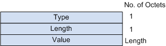
The variable length fields in an IS-IS PDU are multiple type-length-values (TLVs). Figure 5 shows the TLV format. A TLV is also called a code-length-value (CLV).
TLVs vary according to PDU types, as shown in Table 1.
TLV Type |
Name |
Applied PDU Type |
|---|---|---|
1 |
Area Addresses |
IIH, LSP |
2 |
IS Neighbors (LSP) |
LSP |
4 |
Partition Designated Level2 IS |
L2 LSP |
6 |
IS Neighbors (MAC Address) |
LAN IIH |
7 |
IS Neighbors (SNPA Address) |
LAN IIH |
8 |
Padding |
IIH |
9 |
LSP Entries |
SNP |
10 |
Authentication Information |
IIH, LSP, SNP |
128 |
IP Internal Reachability Information |
LSP |
129 |
Protocols Supported |
IIH, LSP |
130 |
IP External Reachability Information |
LSP |
131 |
Inter-Domain Routing Protocol Information |
L2 LSP |
132 |
IP Interface Address |
IIH, LSP |
TLVs with the type value ranging from 1 to 10 are defined in ISO 10589, and the other TLVs are defined in RFC 1195.