IS-IS Local MT
IS-IS local multicast-topology (MT) creates a separate multicast topology on the local device, without affecting the protocol packets exchanged between devices, to allow both TE tunnels and multicast to be configured on the backbone network.

The mentioned TE tunnel specifies the TE tunnel enabled with IGP Shortcut (AA).
Background
When multicast and an MPLS TE tunnel are deployed in a network simultaneously, the multicast function may be affected by the TE tunnel.
This is because after the TE tunnel is enabled with IS-IS Shortcut (AA), the outbound interface of a route calculated by an IS-IS is not the actual physical interface but a TE tunnel interface. According to the unicast route to the multicast source address, a router sends a Report message through a TE tunnel interface. Routers spanned by the TE tunnel cannot sense the Report message, so multicast forwarding entries cannot be created. The TE tunnel is unidirectional, so multicast data packets sent by the multicast source are sent to the routers spanned by the tunnel through the related physical interfaces. The routers do not have any multicast forwarding entry. Therefore, the multicast data packets are discarded.
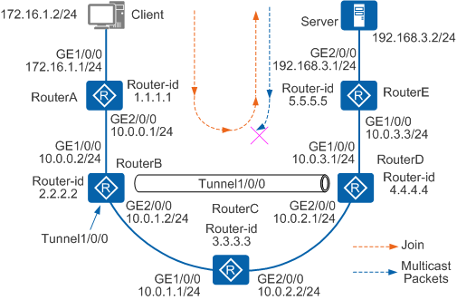
As shown in Figure 1, RouterA, RouterB, RouterC, RouterD, and RouterE are Level-2 routers. The routers run IS-IS to implement interconnection. The multicast services are normal. A unidirectional MPLS TE tunnel is set up between RouterB and RouterD. The MPLS TE tunnel is enabled with IS-IS Shortcut (AA). When you view the multicast routing table on RouterC spanned by the TE tunnel, you cannot find any multicast forwarding entry. Therefore, the multicast services are interrupted.
The process of transmitting multicast packets between the client and the multicast server is as follows:
To join a multicast group, the client sends a Report message to RouterA. RouterA then sends a Join message to RouterB.
When the Join message reaches RouterB, RouterB uses Tunnel 1/0/0 as the Reverse Path Forwarding (RPF) interface and forwards the message to RouterC through GE 2/0/0 by using the MPLS label.
The Join message is forwarded with the MPLS label, so RouterC just forwards the message and does not create a multicast routing entry. In the topology shown in Figure 1, RouterC is the penultimate hop of the MPLS forwarding. RouterC pops out the MPLS label, and then forwards the Join message to RouterD through GE 2/0/0.
After receiving the Join message, RouterD creates a multicast forwarding entry. The inbound interface is GE 2/0/0 and the outbound interface is GE 1/0/0. RouterD then forwards the message to RouterE. The SPT is set up.
When the multicast source sends the traffic to RouterD, RouterD forwards the traffic to RouterC. RouterC does not create any forwarding entry in advance. Therefore, the traffic is discarded and the multicast service is interrupted.
As described in the preceding process of transmitting multicast packets, the forwarding of multicast packets relies on the unicast routing table, and the TE tunnel is unidirectional. Therefore, the multicast packets are discarded. This problem can be avoided by using the following methods:
Manually configuring static multicast routes to guide the forwarding of multicast packets.
Configuring a bidirectional TE tunnel. In this case, the returned multicast packets can be sent by using the same tunnel. Routers spanned by the TE tunnel use the tunnel to transmit multicast packets.
Configuring the Multicast Border Gateway Protocol (MBGP) to separate the unicast topology from the multicast topology. MBGP provides the topology that does not contain the TE tunnel for multicast separately. Multicast is used to perform RPF check on MBGP routes.
Configuring local MT
The preceding methods are used to prevent the interruption of multicast services. The disadvantage of the first three methods is that a lot of manual configurations need to be done. As a result, if the network is complex, the planning, configuration, and maintenance tasks become heavier. Therefore, in the preceding network environment, local MT needs to be configured.
Principles
Local MT creates a separate multicast topology on the local device, without affecting the protocol packets exchanged between devices. This ensures that multicast services are still available when both multicast and the MPLS TE tunnel enabled with IGP Shortcut are deployed.
After local MT is enabled, the router at the ingress of a TE tunnel creates a separate multicast IGP (MIGP) routing table to store the physical interfaces corresponding to the TE tunnel. This ensures that multicast protocol packets are correctly forwarded. The correct routing entries are created in the multicast routing table (MRT). The implementation of local MT can be divided into two stages:
Create an MIGP routing table.
Multicast protocol packets are forwarded according to the unicast routing table. After local MT is enabled on RouterB, RM creates separate MIGP routing tables for multicast protocols. When the outbound interface of a route is a TE tunnel interface, an IGP calculates the actual physical outbound interface for the route and adds the outbound interface to the MIGP routing table.
Guide the forwarding of multicast protocol packets.
Before forwarding a multicast protocol packet, a router needs to search the unicast routing table. If the router finds that the next hop is the TE tunnel, the router continues to search the MIGP routing table for the related physical outbound interface to guide the forwarding of the multicast protocol packet.
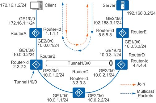
As shown in Figure 2, if the outbound interface of multicast source 192.168.3.2/24 is TE tunnel 1/0/0, the physical outbound interface of the route calculated by IS-IS is GE 2/0/0. IS-IS installs the route to the MIGP routing table. The multicast services are not affected by the TE tunnel. Multicast packets are forwarded through the physical outbound interfaces according to the MIGP routing table for the general IP forwarding. The related routing entries are created in the MRT. Multicast data packets are then correctly forwarded.