OSPF GR
The control plane and forwarding plane are generally separated on switches. When the network topology remains stable, a restart of the control plane does not affect the forwarding plane, which means that the forwarding plane can continue to forward data. This separation ensures non-stop service forwarding.
In graceful restart (GR) mode, the forwarding plane continues to direct data forwarding when a device restart occurs, without being affected by the actions on the control plane, such as re-establishment of neighbor relationships and route calculation. In this way, service interruption caused by route flapping is prevented and the network reliability is improved.
Basic Concepts of OSPF GR
Graceful Restart (GR), also called non-stop forwarding (NSF), is used to ensure normal traffic forwarding and proper running of key services during a routing protocol restart.
Unless otherwise stated, GR described in this section refers to the GR technology defined in RFC 3623.
GR is a fault-tolerant redundancy technology, one of high availability (HA) technologies that include link protection, faulty node recovery, and traffic engineering, and is used to ensure non-stop forwarding of key services during active/standby switchovers and system upgrades.
The following concepts are involved in GR:
Grace-LSA
OSPF supports GR by flooding Grace-LSAs. Grace-LSAs are used to inform neighbors of the GR time, cause, and interface address when the GR starts and ends.
Role of a switch during GR
Restarter: is the switch that restarts. The Restarter can be configured to support full GR or partial GR.
Helper: is the switch that helps the Restarter. The Helper can be configured to:
- Selectively support GR based on policies.
- Support planned GR.
- Support unplanned GR.
GR causes
Unknown: indicates that GR is triggered by unknown events.
Software restart: indicates that GR is triggered by commands.
Software reload/upgrade: indicates that GR is triggered by a software restart or upgrade.
Switch to redundant control processor: indicates that GR is triggered by an abnormal active/standby switchover.
GR period
The GR period cannot exceed 1800 seconds. OSPF switches can exit GR before GR timeout regardless of successful or failed GR.
Classification of OSPF GR
Full GR: When a neighbor of a switch does not support GR, the switch exits GR.
Partial GR: When a neighbor of a switch does not support GR, only the interface associated with this neighbor exits GR, whereas the other interfaces perform GR normally.
Planned GR: Commands are manually configured to restart a switch or perform an active/standby switchover for the switch. The Restarter sends a Grace-LSA before the restart or switchover.
Unplanned GR: A switch performs an active/standby switchover without sending a Grace-LSA and then enters GR after the standby board goes Up. The process of unplanned GR after the standby board goes Up is the same as that of planned GR.
GR Process
Figure 1 shows an OSPF GR process.
An OSPF GR process includes the following phases: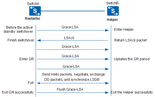
The Restarter (SwitchA) enters the GR state.
The Restarter performs an active/standby switchover.
 In planned GR mode, the Restarter sends a Grace-LSA to notify the Helper of the GR start, period, and cause before performing the switchover. In unplanned GR mode, the Restarter does not send any Grace-LSA.
- Before the Restarter enters the GR state, it sends a Grace-LSA to maintain OSPF neighbor relationships.
When the standby board goes Up, the Restarter immediately sends a Grace-LSA to notify the Helper (SwitchB) of the GR start, period, and cause. Then, the Restarter sends five consecutive Grace-LSAs to the Helper to ensure that the Helper can receive a Grace-LSA.
Sending five consecutive Grace-LSAs is proposed by vendors and has not been defined by OSPF.
During the GR, the Helper retains the neighbor relationship with the Restarter so that other switches do not detect the active/standby switchover performed by the Restarter.
The Restarter stays in the GR state.
- The Restarter and Helper establish an OSPF adjacency.
- The Helper checks the Restarter status. If the Restarter status is Down, the Helper considers that the Restarter can restore services within a specified GR period. Before the specified GR period expires, the Helper does not terminate sessions or delete the topology or routing information obtained from the Restarter.
- When the Restarter recovers, it sends a packet to the Helper. After the Restarter receives a response, it reestablishes the neighbor relationship list.
- The Restarter establishes a session with the Helper to obtain topology or routing information and uses the information to calculate its own routing table.
An active/standby switchover or restart of the Restarter can be manually performed or automatically triggered by faults. During the switchover or restart, the Restarter does not delete the routing information from its routing table or FIB or reset its interface boards. Therefore, the service continuity can be implemented.
The Restarter exits the GR state.
If the GR is successful, the Restarter reestablishes the neighbor relationship with the Helper before the GR period expires. After the Helper receives a Grace-LSA with an aging time of 3600 seconds from the Restarter, the status of the neighbor relationship between the Helper and Restarter changes to Full.
If the GR fails, packet reception and status change on the Restarter and Helper are as follows:
On the Restarter:
The Restarter times out the GR and fails to completely recover the neighbor relationships.
The Restarter fails to perform the bidirectional check due to Type 1 or Type 2 LSAs sent by the Helper.
The interface status of the Restarter changes.
The Restarter receives 1-way Hello packets from the Helper.
The Restarter receives a Grace-LSA generated by another switch on the same network segment.
Only one switch can perform GR on the same network segment at the same time.Different DRs or BDRs are elected among the Restarter and neighbors on the same network segment due to topology changes.
On the Helper:
The Helper fails to receive a Grace-LSA from the Restarter before the neighbor relationship expires.
The interface status of the Helper changes.
The Helper receives LSAs different from those in its own LSDB from other switches. You can configure the Helper not to perform a strict LSA check to avoid this issue.
The Helper receives Grace-LSAs from two switches on the same network segment at the same time.
The neighbor relationships between the Helper and other switches change.
Comparison Between GR Mode and Non-GR Mode
Switchover in Non-GR Mode |
Switchover in GR Mode |
|---|---|
|
|