DR/BDR Election
Router ID
During DR/BDR election, if two routers use the same DR priority, they need to compare their router IDs, and the router with a larger router ID will become the DR or BDR.
A router ID is a 32-bit integer used to uniquely identify an OSPF router in an AS. Each OSPF router has a router ID, which is in the same format as an IP address.
An OSPF router ID can be manually configured or automatically selected. To ensure OSPF stability, you are advised to manually configure the IP address of a loopback interface as the router ID.
If no OSPF router ID is manually configured for a router, the router selects the global router ID as its OSPF router ID. If both the OSPF router ID and global router ID are not configured, the router selects a router ID based on specified rules. For details, see Router ID.
- The ospf command is run to re-configure an OSPF router ID.
- The global router ID is re-configured, and the OSPF process is restarted.
- The IP address of the original global router ID is deleted, and the OSPF process is restarted.
Reason for DR/BDR Election
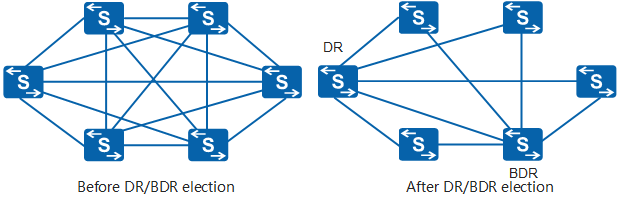
On broadcast and NBMA networks, any two routers need to exchange routing information. As shown in Figure 1, there are n routers that need to establish n x (n - 1)/2 adjacencies. A route change on any router is transmitted to the other routers, which consumes bandwidth resources.
To solve this problem, the concept of DR is defined in OSPF. After a DR is elected, all the other routers send routing information only to the DR, and the DR broadcasts LSAs.
To prevent service interruption caused by DR re-election if the DR fails, a BDR is also elected during DR election. The routers, excluding the DR and BDR, are called DR others. The DR others do not establish adjacencies or exchange any routing information with each other. This reduces the number of adjacencies established between routers on broadcast and NBMA networks.
DR/BDR Election Principles
To ensure stable DR/BDR election on broadcast and NBMA networks, OSPF defines three election principles: election, non-preemption, and inheritance.
Election Principle
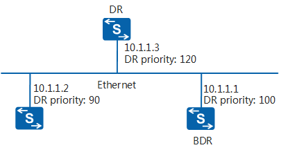
The DR and BDR are not designated manually, but are elected by all routers on the local network segment. In Figure 2, DR priorities of router interfaces determine whether the interfaces are qualified for DR/BDR election. Routers with DR priorities greater than 0 on the local network segment can be considered as candidates. The ballots in this election are performed using Hello packets. Each router adds elected DR information to a Hello packet and sends the packet to other routers on the network segment. When two routers on the same network segment declare that they are the DR, the router with a higher DR priority is elected as the DR. If the two routers have the same DR priority, the router with the greater router ID is elected as the DR. The router whose DR priority is 0 cannot be elected as the DR or BDR.
Non-preemption Principle
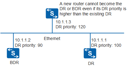
A router newly added to a network segment does not initiate a new election. Instead, it checks whether a DR exists on the network segment. In Figure 3, a DR exists on the network segment. Even if the DR priority of the newly added router is higher than that of the existing DR, the newly added router does not declare itself the DR, and acknowledges the existing DR. Routers on a network segment establish adjacencies only with the DR and BDR. If the DR changes frequently, all routers on the network segment need to establish adjacencies with the new DR and BDR accordingly. As a result, a large number of OSPF packets are transmitted on the network segment within a short period of time, consuming bandwidth resources. The non-preemption principle improves network stability and conserves bandwidth resources. On a broadcast or NBMA network, the two routers that are qualified for DR election and start first become the DR and BDR respectively.
Inheritance Principle
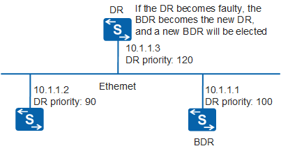
If the DR on a network segment fails, the BDR is elected as the DR, and the other routers compete to become the new BDR, as shown in Figure 4. This principle prevents frequent DR elections and enables the BDR to become the new DR when the DR fails, ensuring the DR stability. Because LSDBs of the DR and BDR are fully synchronized, the BDR can immediately become the new DR when the DR fails, providing the DR functions. The time consumed from role change to service switching is short because adjacencies have been established. Meanwhile, a new BDR will be elected after the original BDR becomes the DR. The new BDR election process consumes a relatively long time, but route calculation is not affected.
DR/BDR Election Process
The DR/BDR election process on a broadcast or NBMA network is as follows:
After an interface goes Up, it sends a Hello packet and enters the Waiting state. In Waiting state, a wait timer is triggered. The wait timer value is the same as the dead timer value. The default wait timer value is 40 seconds and cannot be changed. For details about OSPF interface status, see OSPF Interface State Machine.
Before the wait timer is triggered, sent Hello packets do not contain DR or BDR information. In Waiting state, if a received Hello packet contains DR and BDR information, the interface directly acknowledges the DR and BDR on the network, and does not trigger election. The interface directly exits the Waiting state and starts neighbor synchronization.
Assume that a DR and a BDR exist on the network. A router newly connected to the network acknowledges the existing DR and BDR regardless of its router ID or DR priority.
If the DR fails and goes Down, the BDR takes over the role of the DR. The other routers with DR priorities greater than 0 then compete to become the new BDR.
DR election rules are used to elect a DR only when routers with different router IDs or DR priorities are started at the same time. The election rules state that the device with the highest DR priority is elected as the DR and the device with the second highest DR priority as the BDR. A router with a DR priority of 0 can only be a DR other. If routers have the same DR priority, the router with the largest router ID is elected as the DR, the router with the second largest router ID becomes the BDR, and other routers are DR others.
Verifying the DR/BDR Election Process
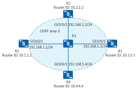
In Figure 5, five routers establish a broadcast network. R5 works as a Layer 2 device, and R1 to R4 work as routers. R1 to R4 are in OSPF area 0.
DR and BDR Are Properly Elected on the Network
Assume that interfaces on R1 to R4 have been configured. Only OSPF configurations are provided here.
R1 configuration
#
ospf 1 Router ID 10.1.1.1
 area 0.0.0.0
  network 192.168.1.0 0.0.0.255
#
R2 configuration
#
ospf 1 Router ID 10.2.2.2
 area 0.0.0.0
  network 192.168.1.0 0.0.0.255
#
R3 configuration
#
ospf 1 Router ID 10.3.3.3
 area 0.0.0.0
  network 192.168.1.0 0.0.0.255
#
R4 configuration
#
ospf 1 Router ID 10.4.4.4
 area 0.0.0.0
  network 192.168.1.0 0.0.0.255
#
After the configurations are complete and the network is stable, check the DR/BDR election status.
# Check OSPF neighbor information on R1. The following command output shows that DR/BDR election has been completed. R1 is the DR, R2 is the BDR, and R3 and R4 are DR others. R1 and R2 are elected as the DR and BDR respectively because of their startup sequence. In this example, R1, R2, R3, and R4 are started consecutively. Therefore, R1 and R2 complete initialization first and become the DR and BDR, respectively.
<R1> display ospf peer

         OSPF Process 1 with Router ID 10.1.1.1
                 Neighbors

 Area 0.0.0.0 interface 192.168.1.1(GigabitEthernet0/0/1)'s neighbors
 Router ID: 10.2.2.2         Address: 192.168.1.2
   State: Full  Mode:Nbr is Master  Priority: 1
   DR: 192.168.1.1  BDR: 192.168.1.2   MTU: 0
   Dead timer due in 38  sec
   Retrans timer interval: 5
   Neighbor is up for 00:22:16
   Authentication Sequence: [ 0 ]

 Router ID: 10.3.3.3         Address: 192.168.1.3
   State: Full  Mode:Nbr is Master   Priority: 1
   DR: 192.168.1.1  BDR: 192.168.1.2   MTU: 0
   Dead timer due in 35  sec
   Retrans timer interval: 5
   Neighbor is up for 00:21:30
   Authentication Sequence: [ 0 ]

 Router ID: 10.4.4.4         Address: 192.168.1.4
   State: Full  Mode:Nbr is Master   Priority: 1
   DR: 192.168.1.1  BDR: 192.168.1.2   MTU: 0
   Dead timer due in 33  sec
   Retrans timer interval: 5
   Neighbor is up for 00:20:24
   Authentication Sequence: [ 0 ]
# Check brief OSPF neighbor information on R1, R2, R3, and R4. The following command output shows that the neighbor relationships between R1 and the other three routers and those between R2 and the other three routers are in Full state, and the neighbor relationship between R3 and R4 is in 2-Way state. The states indicate that the DR and BDR establish adjacencies with other routers, and DR others only establish neighbor relationships with each other. For details about OSPF neighbor status, see OSPF Neighbor State Machine.
<R1> display ospf 1 peer brief

         OSPF Process 1 with Router ID 10.1.1.1
                   Peer Statistic Information
 ----------------------------------------------------------------------------
 Area Id         Interface                  Neighbor id      State
 0.0.0.0         GigabitEthernet0/0/1       10.2.2.2         Full
 0.0.0.0         GigabitEthernet0/0/1       10.3.3.3         Full
 0.0.0.0         GigabitEthernet0/0/1       10.4.4.4         Full
 ----------------------------------------------------------------------------
 Total Peer(s):     3
<R2> display ospf 1 peer brief

         OSPF Process 1 with Router ID 10.2.2.2
                   Peer Statistic Information
 ----------------------------------------------------------------------------
 Area Id         Interface                  Neighbor id      State
 0.0.0.0         GigabitEthernet0/0/1       10.1.1.1         Full
 0.0.0.0         GigabitEthernet0/0/1       10.3.3.3         Full
 0.0.0.0         GigabitEthernet0/0/1       10.4.4.4         Full
 ----------------------------------------------------------------------------
 Total Peer(s):     3
<R3> display ospf 1 peer brief

         OSPF Process 1 with Router ID 10.3.3.3
                   Peer Statistic Information
 ----------------------------------------------------------------------------
 Area Id         Interface                  Neighbor id      State
 0.0.0.0         GigabitEthernet0/0/1       10.1.1.1         Full
 0.0.0.0         GigabitEthernet0/0/1       10.2.2.2         Full
 0.0.0.0         GigabitEthernet0/0/1       10.4.4.4         2-Way
 ----------------------------------------------------------------------------
 Total Peer(s):     3
<R4> display ospf 1 peer brief

         OSPF Process 1 with Router ID 10.4.4.4
                   Peer Statistic Information
 ----------------------------------------------------------------------------
 Area Id         Interface                  Neighbor id      State
 0.0.0.0         GigabitEthernet0/0/1        10.1.1.1         Full
 0.0.0.0         GigabitEthernet0/0/1        10.2.2.2         Full
 0.0.0.0         GigabitEthernet0/0/1        10.3.3.3         2-Way
 ----------------------------------------------------------------------------
 Total Peer(s):     3
BDR Cannot Be Elected on the Network
If the ospf dr-priority command is run on GE0/0/1 of R2, R3, and R4 to set the interface DR priority to 0, the three routers are unqualified for DR/BDR election and can only work as DR others. Only one router (R1) on the network is qualified for DR/BDR election.
# Check OSPF neighbor information on R1. The following command output shows that R1 is the DR. The BDR field is displayed as None, indicating that no BDR exists on the network.
<R1> display ospf peer

         OSPF Process 1 with Router ID 10.1.1.1
                 Neighbors

 Area 0.0.0.0 interface 192.168.1.1(GigabitEthernet0/0/1)'s neighbors
 Router ID: 10.2.2.2         Address: 192.168.1.2
   State: Full  Mode:Nbr is Master  Priority: 0
   DR: 192.168.1.1  BDR: None   MTU: 0
   Dead timer due in 38  sec
   Retrans timer interval: 5
   Neighbor is up for 00:04:31
   Authentication Sequence: [ 0 ]

 Router ID: 10.3.3.3         Address: 192.168.1.3
   State: Full  Mode:Nbr is Master   Priority: 0
   DR: 192.168.1.1  BDR: None   MTU: 0
   Dead timer due in 35  sec
   Retrans timer interval: 5
   Neighbor is up for 00:03:45
   Authentication Sequence: [ 0 ]

 Router ID: 10.4.4.4         Address: 192.168.1.4
   State: Full  Mode:Nbr is Master   Priority: 0
   DR: 192.168.1.1  BDR: None   MTU: 0
   Dead timer due in 33  sec
   Retrans timer interval: 5
   Neighbor is up for 00:03:36
   Authentication Sequence: [ 0 ]
# Check brief OSPF neighbor information on R1, R2, R3, and R4. The following command output shows that R2, R3, and R4 each establish an adjacency with R1, the corresponding states are Full, and the states of neighbor relationships among R2, R3, and R4 are 2-Way.
<R1> display ospf 1 peer brief

         OSPF Process 1 with Router ID 10.1.1.1
                   Peer Statistic Information
 ----------------------------------------------------------------------------
 Area Id         Interface                  Neighbor id      State
 0.0.0.0         GigabitEthernet0/0/1       10.2.2.2         Full
 0.0.0.0         GigabitEthernet0/0/1       10.3.3.3         Full
 0.0.0.0         GigabitEthernet0/0/1       10.4.4.4         Full
 ----------------------------------------------------------------------------
 Total Peer(s):     3
<R2> display ospf 1 peer brief

         OSPF Process 1 with Router ID 10.2.2.2
                   Peer Statistic Information
 ----------------------------------------------------------------------------
 Area Id         Interface                  Neighbor id      State
 0.0.0.0         GigabitEthernet0/0/1       10.1.1.1         Full
 0.0.0.0         GigabitEthernet0/0/1       10.3.3.3         2-Way
 0.0.0.0         GigabitEthernet0/0/1       10.4.4.4         2-Way
 ----------------------------------------------------------------------------
 Total Peer(s):     3
<R3> display ospf 1 peer brief

         OSPF Process 1 with Router ID 10.3.3.3
                   Peer Statistic Information
 ----------------------------------------------------------------------------
 Area Id         Interface                  Neighbor id      State
 0.0.0.0         GigabitEthernet0/0/1       10.1.1.1         Full
 0.0.0.0         GigabitEthernet0/0/1       10.2.2.2         2-Way
 0.0.0.0         GigabitEthernet0/0/1       10.4.4.4         2-Way
 ----------------------------------------------------------------------------
 Total Peer(s):     3
<R4> display ospf 1 peer brief

         OSPF Process 1 with Router ID 10.4.4.4
                   Peer Statistic Information
 ----------------------------------------------------------------------------
 Area Id         Interface                  Neighbor id      State
 0.0.0.0         GigabitEthernet0/0/1       10.1.1.1         Full
 0.0.0.0         GigabitEthernet0/0/1       10.2.2.2         2-Way
 0.0.0.0         GigabitEthernet0/0/1       10.3.3.3         2-Way
 ----------------------------------------------------------------------------
 Total Peer(s):     3
In conclusion, if only one router on a broadcast network is qualified for DR/BDR election, the router becomes the DR, no BDR exists on the network, and all the other routers establish adjacencies only with the DR.
No DR or BDR Can Be Elected on the Network
On the basis of the preceding configuration, if the ospf dr-priority command is executed on GE0/0/1 of R1 to set the interface DR priority to 0, R1 is also unqualified for DR/BDR election. No router on the network is qualified for DR/BDR election.
# Check OSPF neighbor information on R1. The following command output shows that both the DR and BDR fields are displayed as None, indicating that no DR or BDR exists on the network.
<R1> display ospf peer

         OSPF Process 1 with Router ID 10.1.1.1
                 Neighbors

 Area 0.0.0.0 interface 192.168.1.1(GigabitEthernet0/0/1)'s neighbors
 Router ID: 10.2.2.2         Address: 192.168.1.2
   State: Full  Mode:Nbr is Master  Priority: 0
   DR: None  BDR: None   MTU: 0
   Dead timer due in 38  sec
   Retrans timer interval: 5
   Neighbor is up for 00:00:00
   Authentication Sequence: [ 0 ]

 Router ID: 10.3.3.3         Address: 192.168.1.3
   State: Full  Mode:Nbr is Master   Priority: 0
   DR: None  BDR: None   MTU: 0
   Dead timer due in 35  sec
   Retrans timer interval: 5
   Neighbor is up for 00:00:00
   Authentication Sequence: [ 0 ]

 Router ID: 10.4.4.4         Address: 192.168.1.4
   State: Full  Mode:Nbr is Master   Priority: 0
   DR: None  BDR: None   MTU: 0
   Dead timer due in 33  sec
   Retrans timer interval: 5
   Neighbor is up for 00:00:00
   Authentication Sequence: [ 0 ]
# Check brief OSPF neighbor information on R1, R2, R3, and R4. The following command output shows that all neighbor relationships are in 2-Way state, no adjacency can be established on the network, and routers cannot exchange routing information.
<R1> display ospf 1 peer brief

         OSPF Process 1 with Router ID 10.1.1.1
                   Peer Statistic Information
 ----------------------------------------------------------------------------
 Area Id         Interface                  Neighbor id      State
 0.0.0.0         GigabitEthernet0/0/1       10.2.2.2         2-Way
 0.0.0.0         GigabitEthernet0/0/1       10.3.3.3         2-Way
 0.0.0.0         GigabitEthernet0/0/1       10.4.4.4         2-Way
 ----------------------------------------------------------------------------
 Total Peer(s):     3
<R2> display ospf 1 peer brief

         OSPF Process 1 with Router ID 10.2.2.2
                   Peer Statistic Information
 ----------------------------------------------------------------------------
 Area Id         Interface                  Neighbor id      State
 0.0.0.0         GigabitEthernet0/0/1       10.1.1.1         2-Way
 0.0.0.0         GigabitEthernet0/0/1       10.3.3.3         2-Way
 0.0.0.0         GigabitEthernet0/0/1       10.4.4.4         2-Way
 ----------------------------------------------------------------------------
 Total Peer(s):     3
<R3> display ospf 1 peer brief

         OSPF Process 1 with Router ID 10.3.3.3
                   Peer Statistic Information
 ----------------------------------------------------------------------------
 Area Id         Interface                  Neighbor id      State
 0.0.0.0         GigabitEthernet0/0/1       10.1.1.1         2-Way
 0.0.0.0         GigabitEthernet0/0/1       10.2.2.2         2-Way
 0.0.0.0         GigabitEthernet0/0/1       10.4.4.4         2-Way
 ----------------------------------------------------------------------------
 Total Peer(s):     3
<R4> display ospf 1 peer brief

         OSPF Process 1 with Router ID 10.4.4.4
                   Peer Statistic Information
 ----------------------------------------------------------------------------
 Area Id         Interface                  Neighbor id      State
 0.0.0.0         GigabitEthernet0/0/1       10.1.1.1         2-Way
 0.0.0.0         GigabitEthernet0/0/1       10.2.2.2         2-Way
 0.0.0.0         GigabitEthernet0/0/1       10.3.3.3         2-Way
 ----------------------------------------------------------------------------
 Total Peer(s):     3
In conclusion, if no router on a broadcast network is qualified for DR/BDR election, the network has no DR or BDR, and routers on the network do not establish adjacencies. In this case, all neighbor relationships among these routers are in 2-Way state.