OSPF LSA Types
An OSPF network is partitioned into multiple areas. These areas need to maintain their own LSDBs, and routers in these areas are classified into different types. LSAs encapsulated with route description can also be classified based on the router types.
Figure 1 shows an OSPF network that is partitioned into three areas. A static route is configured on R4 and imported into an OSPF process.
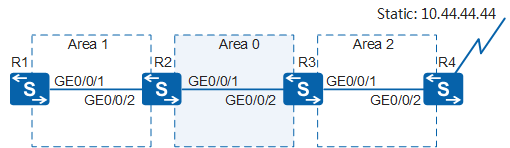
Table 1 lists router IDs and interface IP addresses of R1, R2, R3, and R4.
Device |
Router ID |
Interface IP Address |
|---|---|---|
R1 |
10.1.1.1/32 |
GE0/0/1: 192.168.12.1/24 |
R2 |
10.2.2.2/32 |
GE0/0/2: 192.168.12.2/24 GE0/0/1: 192.168.23.1/24 |
R3 |
10.3.3.3/32 |
GE0/0/2: 192.168.23.2/24 GE0/0/1: 192.168.34.1/24 |
R4 |
10.4.4.4/32 |
GE0/0/2: 192.168.34.2/24 |
The following describes LSA types based on the network shown in Figure 1.
Router-LSA
A Router-LSA is a Type 1 LSA. It describes a router's link state and cost.
Every router on the OSPF network generates Router-LSAs and advertises them within its areas. In Figure 2, R2 advertises a Router-LSA within Area 0 and Area 1.
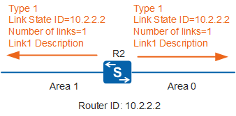
Figure 3 shows the information contained in the Router-LSA flooded by GE0/0/1 on R2.
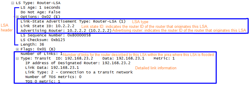
An LSA includes the LSA header and LSA information fields. In all types of LSAs, their LSA header contains the same fields with the only difference of the Link State ID field meaning. You need to focus on the following fields in an LSA header:
Link-State Advertisement Type: indicates the LSA type.
Link State ID: indicates a link state ID. In a Router-LSA, this field indicates the router ID of the device that originates this LSA. Here, the value of this field is the router ID of R2.
Advertising Router: indicates the router that advertises this LSA.
A Router-LSA contains three information fields, which are used to advertise a router's link states and costs to other routers in the area where this LSA is flooded.
The LSA shown in Figure 3 indicates that: The link type (Type) is a transit network (Transit), the DR interface's IP address (ID) is 192.168.23.2, the interface IP address of the advertising router connected to the network is 192.168.23.1 (Data), and the cost (Metric) to this network is 1. Routers that receive this LSA generate the topology based on the link state information.
Four link types area available, and the ID and Data field values vary depending on the link type:
P2P (the field value is 1): The ID field indicates the router ID of a neighbor, and the Data field indicates the interface IP address of the advertising router connected to the network.
Transit (the field value is 2): The ID field indicates the IP address of the DR interface, and the Data field indicates the interface IP address of the advertising router connected to the network.
Stub (the field value is 3): The ID field indicates the IP network or subnet address, and the Data field indicates the network IP address or subnet mask.
Virtual Link (the field value is 4): The ID field indicates the router ID of a neighbor, and the Data field indicates the MIB-II ifIndex of the advertising router's interface.
Network-LSA
A Network-LSA is a Type 2 LSA. It describes the link states of all routers on the local network segment. A DR generates Network-LSAs and advertises them within its area. In Figure 4, R3 sends R2 a Network-LSA that contains router IDs of all the routers that establish adjacencies with the DR.
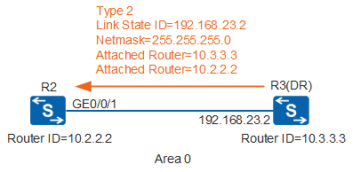
Figure 5 shows the information contained in the Network-LSA.
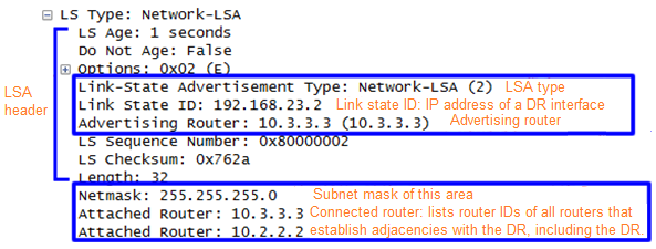
In a Network-LSA, the Link State ID field indicates the IP address of a DR interface.
Flooding Router-LSAs and Network-LSAs within an area enables each router in this area to complete LSDB synchronization, which implements intra-area communication.
Network-summary-LSA
A Network-summary-LSA is a Type 3 LSA. It describes inter-area routing information. An ABR generates Network-summary-LSAs and advertises them within its area to notify destination addresses of routes from this area to other areas. Actually, an ABR generates Network-summary-LSAs by collecting Type 1 and Type 2 LSAs within its area and summarizing related routes. In Figure 6, R2 functions as an ABR to advertise routing information in Area 0 and Area 1 to Area 1 and Area 0 respectively.
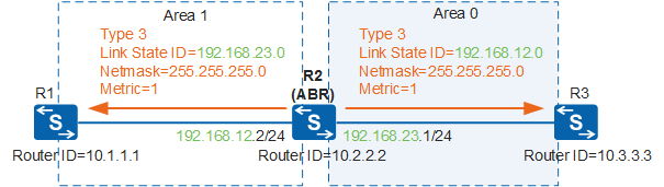
Figure 7 shows the information contained in a Network-summary-LSA advertised by R2 on GE0/0/1.
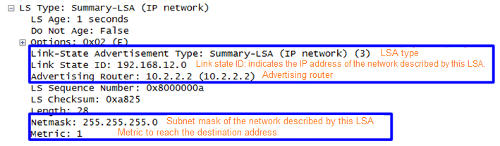
In a Network-summary-LSA, the Link State ID field indicates the IP address of the network described by this LSA. Information in this LSA shows that this LSA is advertised by R2 (10.2.2.2) and can reach the network with the IP address 192.168.12.0 and the subnet mask 255.255.255.0 at the cost of 1. R2 advertises the network address of Area 1 to Area 0 so that routers in Area 0 know how to reach the network in Area 1, implementing inter-area communication.
If an ABR has multiple routes within its area to reach a destination, it originates only one Network-summary-LSA carrying the route with the lowest cost to the backbone area.
Network-summary-LSAs will not be advertised within totally stub areas or totally NSSAs.
ASBR-Summary-LSA
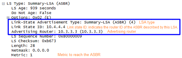
An ASBR-summary-LSA is a Type 4 LSA. It describes routes to an ASBR. An ABR generates ASBR-summary-LSAs and advertises them to areas except the area to which the ASBR is located. In Figure 8, R3 functions as an ABR to advertise an ASBR-summary-LSA to Area 0.
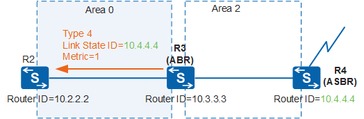
Figure 9 shows information contained in an ASBR-summary-LSA. The Link State ID field indicates the router ID (10.4.4.4) of the ASBR that this LSA describes, namely, R4. The router that advertises this LSA is R3 (10.3.3.3), and the cost of the route from R3 to R4 is 1.
AS-external-LSA
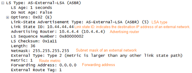
An AS-external-LSA is a Type 5 LSA. It describes routes to destinations outside an AS. An ASBR generates AS-external-LSAs and advertises them to all areas except stub areas and NSSAs. In Figure 10, R4 functions as an ASBR to advertise a route to an external destination network outside the AS.
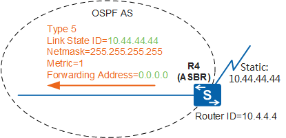
Figure 11 shows the information contained in an AS-external-LSA. The Link State ID field indicates the destination IP address of the external network. The Forwarding Address field indicates the address to which packets destined for this external network should be forwarded. Here, the forwarding address 0.0.0.0 indicates that packets will be forwarded to the ASBR that generates this LSA.
NSSA LSA
In addition to the preceding LSAs, there is a special type of LSA, namely, NSSA LSA. An NSSA LSA is a Type 7 LSA. It describes routes to destinations outside an AS. An ASBR generates NSSA LSAs and advertises them only in NSSAs. When an ABR in an NSSA receives NSSA LSAs, the ABR selectively translates them into Type 5 LSAs to advertise imported external routes to other areas on the OSPF network.
If Area 2 in Figure 1 is an NSSA, GE0/0/2 of R4 generates an NSSA LSA, as shown in Figure 12.
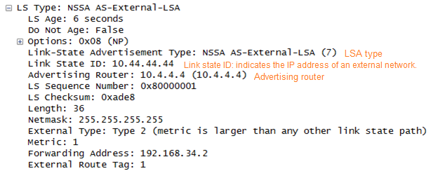
NSSA LASs and AS-external-LSAs have the same fields but are flooded into different areas. AS-external-LSAs are flooded within an AS, whereas NSSA LSAs are flooded within NSSAs.
NSSAs allow importing external routes, but NSSA LSAs describing external routes can only be flooded within NSSAs. To enable external routes to be imported into all areas except NSSAs, the ABR (R3) translates NSSA LSAs into AS-external-LSAs and floods the AS-external-LSAs within the entire AS. The following provides more information about the translation:
- The propagate bit (P-bit) in Type 7 LSAs is used to notify a router of whether the Type 7 LSAs need to be translated.
- By default, the translator is the ABR with the largest router ID in the NSSA.
- Only NSSA LSAs with the P-bit set to 1 and a non-zero forwarding address (FA) can be translated into AS-external-LSAs. An FA indicates a specific address that a packet will be forwarded to before arriving at the destination address.
- The P-bit is not set for default routes in NSSA LSAs generated by an ABR.
Opaque LSA
Opaque LSAs include Type 9 LSAs, Type 10 LSAs, and Type 11 LSAs. They provide a universal mechanism for OSPF extensions.
- Type 9 LSAs are advertised only on the network segment where the originating interface resides. Grace LSAs used to support graceful restart (GR) are Type 9 LSAs.
- Type 10 LSAs are advertised within an OSPF area. LSAs used to support traffic engineering (TE) are Type 10 LSAs.
- Type 11 LSAs are advertised within an AS. At present, there are no applications of Type 11 LSAs.
Table 2 describes whether a type of LSA is supported in an area.
Area Type |
Router-LSA (Type 1) |
Network-LSA (Type 2) |
Network-summary-LSA (Type 3) |
ASBR-summary-LSA (Type 4) |
AS-external-LSA (Type 5) | NSSA-LSA (Type 7) |
|---|---|---|---|---|---|---|
Common area (including standard and backbone areas) |
Supported | Supported | Supported | Supported | Supported | Not supported |
Stub area |
Supported | Supported | Supported | Not supported | Not supported | Not supported |
Totally stub area |
Supported | Supported | Not supported | Not supported | Not supported | Not supported |
NSSA |
Supported | Supported | Supported | Not supported | Not supported | Supported |
| Totally NSSA | Supported | Supported | Not supported | Not supported | Not supported | Supported |