OSPF Network Design Deployment Case
Figure 1 shows a typical campus network topology. This is a large campus network with the core, aggregation, and access layers and multiple egresses to the Internet. On this network, dual-link redundancy and cluster protection among core and aggregation switches have been deployed. Typically, on such a large campus network, Huawei NE series high-end routers are deployed as egress devices, and Huawei campus cluster-supporting modular switches are deployed as core and aggregation switches. User gateways are deployed on the aggregation layer, and aggregation switches are the boundary between Layer 2 and Layer 3 networks.
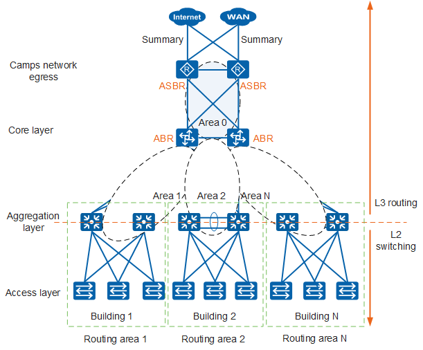
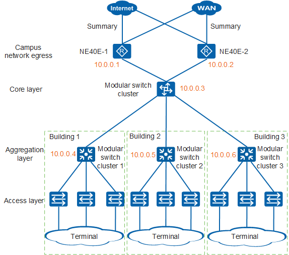
Core and aggregation switches on the typical campus network are deployed in clusters, and one cluster functions as a single logical device. Multiple links are bundled together to form a single logical link. The above network topology is simplified into a logical topology, as shown in Figure 2. There may be multiple buildings in a campus network, and the following example uses three buildings.

OSPF Network Stability: Router ID Design
The primary task of deploying OSPF is to design and deploy router IDs. In most situations, an appropriate private IP address segment can be used to design router IDs. This example uses IP addresses on the IP address segment 10.0.0.0/24 as router IDs.
After router IDs are designed, you need to create loopback interfaces on each OSPF device and configure an IP address 10.0.0.X/32 for each loopback interface.
The following configures router IDs for a core modular switch cluster:
[HUAWEI] interface LoopBack 0
[HUAWEI-LoopBack0] ip address 10.0.0.3 32  //Configure an IP address with a 32-bit mask for LoopBack0.
[HUAWEI-LoopBack0] quit
[HUAWEI] ospf 1 router-id 10.0.0.3  //Create OSPF process 1 and set the router ID to 10.0.0.3.

If there are no special requirements, advertisement of the IP address of Loopback0 into OSPF processes is not recommended because the advertisement is unnecessary.
Figure 3 shows the network topology with router IDs designed.
Hierarchical Network Design: OSPF Area Design
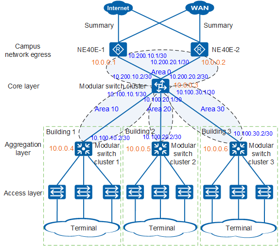
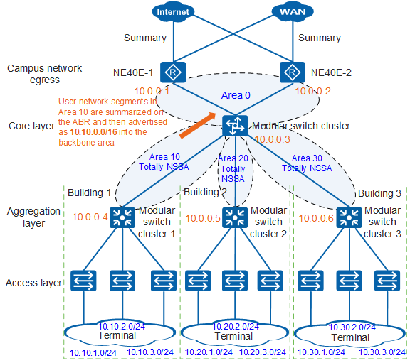
After router IDs are assigned to routers, you need to partition the OSPF network. To obtain a hierarchical OSPF network, you can deploy egress routers and core switches in Area 0 and design non-backbone areas based on geographical locations. When designing area IDs for non-backbone areas, you need to ensure that new areas are easy to add for network expansion. Based on geographical locations involved in this case, egress routers and core switches are deployed in the backbone area and the aggregation switches in each building are deployed in a non-backbone area respectively. Figure 4 shows the OSPF network topology after area partitioning.
The following configures Area 0 and Area 10 for the core switch cluster:
[HUAWEI] ospf 1  //Enter the OSPF process view.
[HUAWEI-ospf-1] area 0  //Enter the view of Area 0.
[HUAWEI-ospf-1-area-0.0.0.0] network 10.200.10.0 0.0.0.3  //Advertise the network segment where the uplink interface resides to Area 0.
[HUAWEI-ospf-1-area-0.0.0.0] network 10.200.20.0 0.0.0.3  //Advertise the network segment where the uplink interface resides to Area 0.
[HUAWEI-ospf-1-area-0.0.0.0] quit
[HUAWEI-ospf-1] area 10  //Enter the view of Area 10.
[HUAWEI-ospf-1-area-0.0.0.10] network 10.100.10.0 0.0.0.3  //Advertise the network segment where the downlink interface resides to Area 10.
[HUAWEI-ospf-1-area-0.0.0.10] quit
The preceding configuration commands show that an OSPF device is located on the border between OSPF areas. The uplink and downlink interfaces of the core switch cluster in the topology belong to Area 0 and Area 10 respectively. That is, this cluster functions as an ABR.
It is a bad design to deploy many low-end routers or Layer 3 switches in a single OSPF area, and it is better to reduce the number of devices in a single OSPF area.
Routing Entry Optimization for Non-Backbone Areas: Special Areas
After the OSPF network is partitioned into multiple areas, you may find that the routing table size of devices in non-backbone areas is large. If devices in non-backbone areas have low performance and are expected not to maintain a large routing table, you can use special areas to reduce the number of routing entries in the table. Figure 5 shows the network topology with all non-backbone areas configured as totally NSSAs.
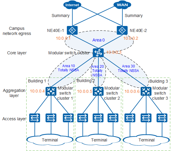
The following provides an example of configuring totally NSSAs by configuring a core switch cluster and an aggregation switch cluster in Area 10.
The configuration of the core switch cluster is as follows:
[HUAWEI] ospf 1  //Enter the OSPF process view.
[HUAWEI-ospf-1] area 10  //Enter the view of Area 10.
[HUAWEI-ospf-1-area-0.0.0.10] nssa no-summary  //Configure nssa no-summary for the ABR.
[HUAWEI-ospf-1-area-0.0.0.10] quit
The configuration of the aggregation switch cluster is as follows:
[HUAWEI] ospf 1  //Enter the OSPF process view.
[HUAWEI-ospf-1] area 10  //Enter the view of Area 10.
[HUAWEI-ospf-1-area-0.0.0.10] nssa  //Configure nssa for the non-ABR.
[HUAWEI-ospf-1-area-0.0.0.10] quit
Before a totally NSSA is configured, routing entries from the aggregation switch cluster to non-backbone areas are as follows:
<HUAWEI> display ip routing-table
Route Flags: R - relay, D - download to fib, T - to vpn-instance
------------------------------------------------------------------------------
Routing Tables: Public
         Destinations : 21        Routes : 21

Destination/Mask    Proto   Pre  Cost      Flags NextHop         Interface

      10.0.0.4/32   Direct  0    0           D   127.0.0.1       LoopBack0
     10.10.1.0/24   Direct  0    0           D   10.10.1.1       Vlanif100
     10.10.1.1/32   Direct  0    0           D   127.0.0.1       Vlanif100
     10.10.2.0/24   Direct  0    0           D   10.10.2.1       Vlanif200
     10.10.2.1/32   Direct  0    0           D   127.0.0.1       Vlanif200
     10.10.3.0/24   Direct  0    0           D   10.10.3.1       Vlanif300
     10.10.3.1/32   Direct  0    0           D   127.0.0.1       Vlanif300
     10.20.1.0/24   OSPF    10   3           D   10.100.10.1     Vlanif10
     10.20.2.0/24   OSPF    10   3           D   10.100.10.1     Vlanif10
     10.20.3.0/24   OSPF    10   3           D   10.100.10.1     Vlanif10
     10.30.1.0/24   OSPF    10   3           D   10.100.10.1     Vlanif10
     10.30.2.0/24   OSPF    10   3           D   10.100.10.1     Vlanif10
     10.30.3.0/24   OSPF    10   3           D   10.100.10.1     Vlanif10
   10.100.10.0/30   Direct  0    0           D   10.100.10.2     Vlanif10
   10.100.10.2/32   Direct  0    0           D   127.0.0.1       Vlanif10
   10.100.20.0/30   OSPF    10   2           D   10.100.10.1     Vlanif10
   10.100.30.0/30   OSPF    10   2           D   10.100.10.1     Vlanif10
   10.200.10.0/30   OSPF    10   2           D   10.100.10.1     Vlanif10
   10.200.20.0/30   OSPF    10   2           D   10.100.10.1     Vlanif10
      127.0.0.0/8   Direct  0    0           D   127.0.0.1       InLoopBack0
      127.0.0.1/32  Direct  0    0           D   127.0.0.1       InLoopBack0
After a totally NSSA is configured, routing entries from the aggregation switch cluster to non-backbone areas are as follows:
<HUAWEI> display ip routing-table
Route Flags: R - relay, D - download to fib, T - to vpn-instance
------------------------------------------------------------------------------
Routing Tables: Public
         Destinations : 12        Routes : 12

Destination/Mask    Proto   Pre  Cost      Flags NextHop         Interface

       0.0.0.0/0    OSPF    10   2           D   10.100.10.1     Vlanif10
      10.0.0.4/32   Direct  0    0           D   127.0.0.1       LoopBack0
     10.10.1.0/24   Direct  0    0           D   10.10.1.1       Vlanif100
     10.10.1.1/32   Direct  0    0           D   127.0.0.1       Vlanif100
     10.10.2.0/24   Direct  0    0           D   10.10.2.1       Vlanif200
     10.10.2.1/32   Direct  0    0           D   127.0.0.1       Vlanif200
     10.10.3.0/24   Direct  0    0           D   10.10.3.1       Vlanif300
     10.10.3.1/32   Direct  0    0           D   127.0.0.1       Vlanif300
   10.100.10.0/30   Direct  0    0           D   10.100.10.2     Vlanif10
   10.100.10.2/32   Direct  0    0           D   127.0.0.1       Vlanif10
      127.0.0.0/8   Direct  0    0           D   127.0.0.1       InLoopBack0
      127.0.0.1/32  Direct  0    0           D   127.0.0.1       InLoopBack0
The preceding outputs show that the IP routing table size of Area 10 is reduced significantly after a totally NSSA is configured. This indicates that configuring a non-backbone area as a totally NSSA can reduce the routing table size.
Routing Entry Optimization for the Backbone Area: IP Subnetting and Route Summarization in Non-Backbone Areas
After non-backbone areas are configured as totally NSSAs, the routing table size of routers in non-backbone areas are reduced significantly and the amount of information to be exchanged between these routers is also reduced. Reduced routing table size and information exchange are also required in the backbone area. To implement this requirement, you need to use IP subnetting and perform route summarization on ABRs in non-backbone areas.
Figure 6 shows summarized routes advertised from Area 10 to Area 0 after IP subnetting is performed.
Route summarization will prevent specific routes from being advertised. The ABR in Area 10 advertises only one summarized route 10.10.0.0/16 into Area 0, reducing the routing entries on the backbone routers and number of OSPF packets to be exchanged with Area 0 and ensuring the routing table stability. Proper IP addressing facilitating route summarization is recommended during OSPF network design.
The following configures route summarization on the ABR (core switch cluster) in Area 10:
[HUAWEI] ospf 1  //Enter the OSPF process view.
[HUAWEI-ospf-1] area 10  //Enter the view of Area 10.
[HUAWEI-ospf-1-area-0.0.0.10] abr-summary 10.10.0.0 255.255.0.0  //Summarize routes on the ABR.
[HUAWEI-ospf-1-area-0.0.0.10] quit
The abr-summary command can be configured only on an ABR. Do not configure this command on non-ABRs in an area. Otherwise, incorrect routing entries will be generated.
Before routes are summarized, the IP routing table of NE40E-1 is as follows:
<NE40E-1> display ip routing-table
Route Flags: R - relay, D - download to fib, T - to vpn-instance
------------------------------------------------------------------------------
Routing Tables: Public
         Destinations : 12        Routes : 12

Destination/Mask    Proto   Pre  Cost      Flags NextHop         Interface

      10.0.0.1/32   Direct  0    0           D   127.0.0.1       LoopBack0
     10.10.1.0/24   OSPF    10   3           D   10.200.10.2     GigabitEthernet0/0/1
     10.10.2.0/24   OSPF    10   3           D   10.200.10.2     GigabitEthernet0/0/1
     10.10.3.0/24   OSPF    10   3           D   10.200.10.2     GigabitEthernet0/0/1
After routes are summarized, the IP routing table of NE40E-1 is as follows:
<NE40E-1> display ip routing-table
Route Flags: R - relay, D - download to fib, T - to vpn-instance
------------------------------------------------------------------------------
Routing Tables: Public
         Destinations : 12        Routes : 12

Destination/Mask    Proto   Pre  Cost      Flags NextHop         Interface

      10.0.0.1/32   Direct  0    0           D   127.0.0.1       LoopBack0
     10.10.0.0/16   OSPF    10   3           D   10.200.10.2     GigabitEthernet0/0/1
The preceding outputs show that NE40E-1 in the backbone area has specific routes to users' network segments before routes are summarized. After route summarization is configured on the ABR, NE40E-1 has only one summarized route with a 16-bit mask to users' network segments. If there are many user network segments, route summarization can significantly reduce routing entries in the backbone areas, decrease the number of LSAs to be exchanged between the backbone and non-backbone areas, and therefore improve the network stability.
Uplink Traffic Diversion: Default OSPF Route Import and Route Selection Optimization
Most traffic of a campus network is destined for the Internet. Therefore, on a campus network with multiple egresses, you must consider importing default routes and load balancing traffic among these egresses.
Multiple methods are available to import default routes. The recommended method is to configure non-forcible delivery of default routes on an ASBR. Non-forcible delivery of default routes indicates that a default route can be advertised only when it exists in the IP routing table of this ASBR. This prevents loops and suboptimal routes in special scenarios.
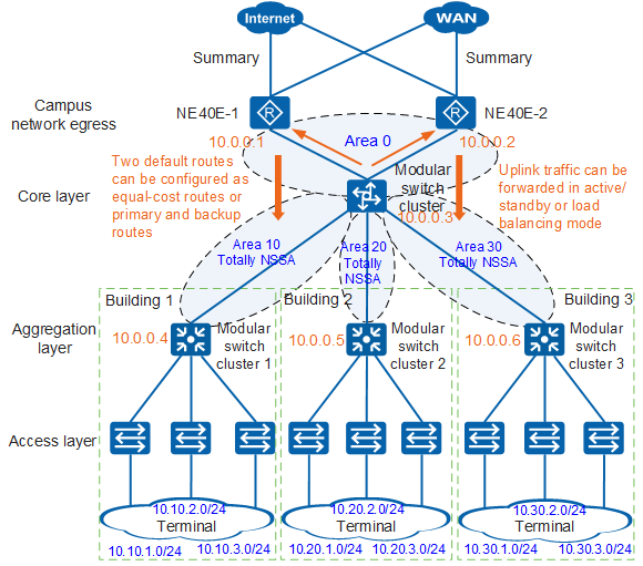
In Figure 7, after two ASBRs advertise default routes, the core switch cluster receives two default routes with their next hops pointing to two egress routers respectively. The core switch cluster can choose one link as the uplink or two uplinks for load balancing. You can flexibly configure traffic direction based on network requirements.
The following configures non-forcible delivery of default routes on NE40E-1 (the configuration of NE40E-2 is similar to that of NE40E-1):
[NE40E-1] ip route-static 0.0.0.0 0.0.0.0 202.10.10.1  //On NE40E-1, configure a default route with the next hop pointing to the public address of the telecom carrier.
[NE40E-1] ospf 1  //Enter the OSPF process view.
[NE40E-1-ospf-1] default-route-advertise  //Advertise the default route without specifying the always parameter. That is, the default route is delivered non-forcibly.
After the preceding configurations are complete, the core switch cluster learns two equal-cost default routes. Uplink traffic of the core switch cluster will be forwarded in load balancing mode.
<HUAWEI> display ip routing-table
Route Flags: R - relay, D - download to fib, T - to vpn-instance
------------------------------------------------------------------------------
Routing Tables: Public
         Destinations : 23        Routes : 24

Destination/Mask    Proto   Pre  Cost      Flags NextHop         Interface

      0.0.0.0/0     O_ASE   150  1           D   10.200.10.1     Vlanif40
                    O_ASE   150  1           D   10.200.20.1     Vlanif50
......
If you want two uplinks of the core switch cluster to work in active/standby mode, the simplest method is to change their OSPF costs.
To implement route backup, you can change the OSPF cost of the link from the core switch cluster to NE40-2 to be higher than that of the link from the cluster to NE40-1. In this way, uplink traffic is preferentially sent to NE40E-1. If NE40E-1 is faulty, the traffic is automatically switched to NE40E-2.
Configure the core switch cluster.
[HUAWEI] interface vlanif 50  //Enter the OSPF interface view.
[HUAWEI-Vlanif50] ospf cost 10  //Change the OSPF cost of this interface to 10.
Configure NE40E-2.
[NE40E-2] interface gigabitethernet 0/0/1  //Enter the OSPF interface view.
[NE40E-2-GigabitEthernet0/0/1] ospf cost 10  //Change the OSPF cost of this interface to 10.
To adjust the cost of a link to affect OSPF route selection, you need to adjust the cost on the devices on both ends of the link. Otherwise, asymmetric routing occurs, which causes network faults.
The default OSPF cost of links providing more than 100 Mbit/s bandwidth is 1. After the OSPF cost of the link from the core switch cluster to NE40-2 is changed to 10, the cluster transmits its uplink traffic preferentially to NE40-1, and the IP routing table of the cluster has only one default route pointing to NE40E-1.
<HUAWEI> display ip routing-table
Route Flags: R - relay, D - download to fib, T - to vpn-instance
------------------------------------------------------------------------------
Routing Tables: Public
         Destinations : 23        Routes : 23

Destination/Mask    Proto   Pre  Cost      Flags NextHop         Interface

      0.0.0.0/0     O_ASE   150  1           D   10.200.10.1     Vlanif40
......
Loop Prevention in Route Summarization Scenarios: Blackhole Route
After the preceding design and deployment, this campus network has basic OSPF functions and routing entries have been optimized. However, this network has the risk of loops due to route summarization.
It is common that a campus network is under internal network attacks. Assume that a host in Building 1 is attacked by viruses, which will make the host access all IP addresses on the network segment 10.0.0.0. In this situation, a loop may easily occur.
If the host accesses the IP address 10.10.50.1 (this address does not exist in Building 1), a routing loop occurs:
When the host sends a packet, the packet is sent to its gateway, namely, aggregation switch cluster 1 in Building 1.
Aggregation switch cluster 1 does not have specific routes to the destination address of this packet, and therefore it sends this packet to the core switch cluster through a default route.
The IP address 10.10.50.1 does not exist on the entire campus network. Therefore, after the packet reaches the core switch cluster, it matches only a default route and then is sent to NE40E-1.
The route learned by NE40E-1 is summarized and then advertised by the core switch cluster, so the packet matches the route 10.10.0.0/16 and is sent back to the core switch cluster.
A routing loop occurs between the core switch cluster and NE40E-1, as shown in Figure 8. This loop will seriously affect network operation and even cause network crash. Therefore, you need to avoid routing loops in route summarization scenarios.
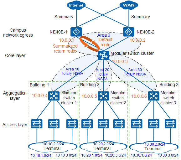
The main reason for this routing loop is that the core switch cluster uses a default route to forward a packet with a destination address that does not exist in the campus network to the backbone area, and then the backbone area sends the packet back to the cluster through a summarized return route.
To address this problem, you need to configure a blackhole route on the core switch cluster to block such a packet. Perform the following configuration:
[HUAWEI] ip route-static 10.10.0.0 255.255.0.0 NULL0
After a blackhole route is configured, the packet to be returned to the network segment 10.10.0.0 will be directed to the user network segment through a specific route. If such specific route is not found, this host address does not exist in the campus network. The packet will match this blackhole route and be dropped to prevent routing loops. When configuring route summarization in other areas, you also need to configure a blackhole route to prevent routing loops.
OSPF Network Security: Silent Interface
After the preceding deployment is completed, the entire OSPF network can run properly. However, this network has a large security vulnerability. That is, user-side interfaces can receive OSPF Hello packets, so basic network information can be easily obtained using a network sniffing tool for attack launch.
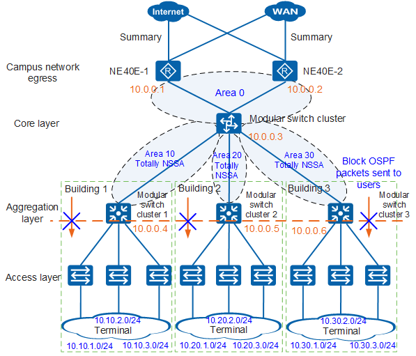
To ensure OSPF network security, you are advised to configure silent interfaces to block OSPF packets sent to users, as shown in Figure 9.
The following configures silent interfaces in core switch cluster 1 in Area 10:
[HUAWEI] ospf 1
[HUAWEI-ospf-1] silent-interface vlanif100
[HUAWEI-ospf-1] silent-interface vlanif200
[HUAWEI-ospf-1] silent-interface vlanif300
The silent-interface command prohibits specified interfaces from receiving and sending OSPF packets and is typically configured on user-side interfaces. Configuring this command on the link between two OSPF routers will cause a failure to establish an OSPF neighbor relationship between them.