Filter-Policy Implementation and Applications
Overview
A filter-policy is a commonly used routing information filtering tool. In Figure 1, SwitchA, SwitchB, and SwitchC run a routing protocol, and routes are transmitted among these devices. A filter-policy can be used to filter specific routing information as required.
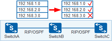

Filter-policies can only filter routing information and cannot filter LSAs or change route attributes.
Filtering Rules
Distance-vector routing protocols (such as RIP) and link-state routing protocols (such as OSPF) vary in principles. Therefore, filter-policy filtering rules vary between the two types of routing protocols. The following table lists differences in routing information transmission between distance-vector routing protocols and link-state routing protocols.
Routing Protocol Type |
Route Transmission Principles |
|---|---|
Distance-vector routing protocols |
Routing devices transmit routing information. This routing information is like roadmap for packets. The devices guide packet forwarding based on the roadmap. |
Link-state routing protocols |
Routing devices transmit link state advertisements (LSAs). A link state database (LSDB) is a set of LSAs and describes the entire network topology, which is like a map. The devices find the optimal forwarding path for packets based on the map and shortest path algorithm. |
Filter-policy in distance-vector routing protocols
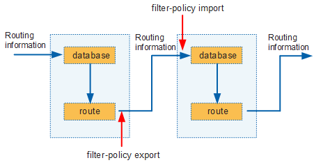
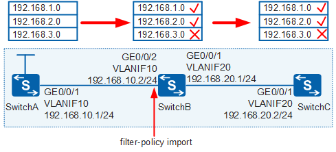
In Figure 2, when using distance-vector routing protocols, devices transmit routing information. To filter the routing information, use a filter-policy. Figure 2 shows where a filter-policy takes effect in the inbound and outbound directions. To filter the routing information transmitted from an upstream device to a downstream device, you only need to configure filter-policy export on the upstream device or configure filter-policy import on the downstream device.
Filter-policy in link-state routing protocols
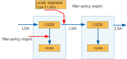
In Figure 3, when using link-state routing protocols, routing devices transmit LSAs and then calculate their routing tables based on the LSDB. The following uses OSPF as an example to describe filter-policy filtering rules:
- The filter-policy import command filters the routes calculated by OSPF but not the LSAs advertised and received.
- The filter-policy export command filters the imported routes to be advertised so that only eligible external routes are translated into Type 5 LSAs (AS-external-LSAs) and advertised. In this manner, imported external routes can be filtered as required to prevent routing loops.
Using a Filter-Policy to Filter the Routes Advertised by RIP
Requirement Description
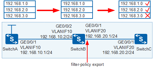
In Figure 4, three switches exchange routes through RIP. Three static routes (used as test routes) are imported into the RIP process of SwitchA. It is required that the filter-policy export command be configured on SwitchB to filter the routes advertised to SwitchC, that is, deny the route 192.168.3.0/24 and permit other routes.
Configuration
Define an IP prefix list on SwitchB to filter routes as required.
[SwitchB] ip ip-prefix huawei index 10 deny 192.168.3.0 24       //Deny this route.
[SwitchB] ip ip-prefix huawei index 20 permit 0.0.0.0 0 less-equal 32    //Permit all routes.
Configure the filter-policy export command in the RIP view of SwitchB.
[SwitchB] rip
[SwitchB-rip-1] filter-policy ip-prefix huawei export Vlanif20
Verification
After the preceding configurations are complete, check the IP routing tables of SwitchB and SwitchC.
[SwitchB] display ip routing-table
Route Flags: R - relay, D - download to fib, T - to vpn-instance
-----------------------------------------------------------------------------
Routing Tables: Public
         Destinations : 9        Routes : 9

Destination/Mask    Proto   Pre  Cost      Flags NextHop         Interface

      127.0.0.0/8   Direct  0    0           D   127.0.0.1       InLoopBack0
      127.0.0.1/32  Direct  0    0           D   127.0.0.1       InLoopBack0
    192.168.1.0/24  RIP     100  1           D   192.168.10.1    Vlanif10
    192.168.2.0/24  RIP     100  1           D   192.168.10.1    Vlanif10
    192.168.3.0/24  RIP     100  1           D   192.168.10.1    Vlanif10
   192.168.10.0/24  Direct  0    0           D   192.168.10.2    Vlanif10
   192.168.10.2/32  Direct  0    0           D   127.0.0.1       Vlanif10
   192.168.20.0/24  Direct  0    0           D   192.168.20.1    Vlanif20
   192.168.20.1/32  Direct  0    0           D   127.0.0.1       Vlanif20
[SwitchC] display ip routing-table
Route Flags: R - relay, D - download to fib, T - to vpn-instance
-----------------------------------------------------------------------------
Routing Tables: Public
         Destinations : 7        Routes : 7

Destination/Mask    Proto   Pre  Cost      Flags NextHop         Interface

      127.0.0.0/8   Direct  0    0           D   127.0.0.1       InLoopBack0
      127.0.0.1/32  Direct  0    0           D   127.0.0.1       InLoopBack0
    192.168.1.0/24  RIP     100  2           D   192.168.20.1    Vlanif20
    192.168.2.0/24  RIP     100  2           D   192.168.20.1    Vlanif20
   192.168.10.0/24  RIP     100  1           D   192.168.20.1    Vlanif20
   192.168.20.0/24  Direct  0    0           D   192.168.20.2    Vlanif20
   192.168.20.2/32  Direct  0    0           D   127.0.0.1       Vlanif20
The preceding command output shows that after the filter-policy export command is configured on SwitchB, SwitchB still has a complete IP routing table; however, SwitchC cannot learn the route 192.168.3.0/24 through RIP because this route has been filtered out before being advertised by SwitchB.
Using a Filter-Policy to Filter the Routes Received by RIP
Requirement Description
In Figure 5, three switches exchange routes through RIP. Three static routes (used as test routes) are imported into the RIP process of SwitchA. It is required that the filter-policy import command be configured on SwitchB to deny the route 192.168.3.0/24 and permit other routes.
Configuration
Define an IP prefix list on SwitchB to filter routes as required.
[SwitchB] ip ip-prefix huawei index 10 deny 192.168.3.0 24      //Deny this route.
[SwitchB] ip ip-prefix huawei index 20 permit 0.0.0.0 0 less-equal 32   //Permit all routes.
Configure the filter-policy import command in the RIP view of SwitchB.
[SwitchB] rip
[SwitchB-rip-1] filter-policy ip-prefix huawei import Vlanif10
Verification
After the preceding configurations are complete, check the IP routing tables of SwitchB and SwitchC.
[SwitchB] display ip routing-table
Route Flags: R - relay, D - download to fib, T - to vpn-instance
-----------------------------------------------------------------------------
Routing Tables: Public
         Destinations : 8        Routes : 8

Destination/Mask    Proto   Pre  Cost      Flags NextHop         Interface

      127.0.0.0/8   Direct  0    0           D   127.0.0.1       InLoopBack0
      127.0.0.1/32  Direct  0    0           D   127.0.0.1       InLoopBack0
    192.168.1.0/24  RIP     100  1           D   192.168.10.1    Vlanif10
    192.168.2.0/24  RIP     100  1           D   192.168.10.1    Vlanif10
   192.168.10.0/24  Direct  0    0           D   192.168.10.2    Vlanif10
   192.168.10.2/32  Direct  0    0           D   127.0.0.1       Vlanif10
   192.168.20.0/24  Direct  0    0           D   192.168.20.1    Vlanif20
   192.168.20.1/32  Direct  0    0           D   127.0.0.1       Vlanif20
[SwitchC] display ip routing-table
Route Flags: R - relay, D - download to fib, T - to vpn-instance
-----------------------------------------------------------------------------
Routing Tables: Public
         Destinations : 7        Routes : 7

Destination/Mask    Proto   Pre  Cost      Flags NextHop         Interface

      127.0.0.0/8   Direct  0    0           D   127.0.0.1       InLoopBack0
      127.0.0.1/32  Direct  0    0           D   127.0.0.1       InLoopBack0
    192.168.1.0/24  RIP     100  2           D   192.168.20.1    Vlanif20
    192.168.2.0/24  RIP     100  2           D   192.168.20.1    Vlanif20
   192.168.10.0/24  RIP     100  1           D   192.168.20.1    Vlanif20
   192.168.20.0/24  Direct  0    0           D   192.168.20.2    Vlanif20
   192.168.20.2/32  Direct  0    0           D   127.0.0.1       Vlanif20
The preceding command output shows that after the filter-policy import command is configured on SwitchB, the IP routing tables of SwitchB and SwitchC do not contain the route 192.168.3.0/24.
RIP is a distance-vector routing protocol and a RIP device advertises its routing table to its neighbors. When the route 192.168.3.0/24 is filtered out from the IP routing table of SwitchB, SwitchC can no longer learn this route through RIP. That is, if routes in an IP routing table of a RIP device are filtered, the IP routing tables of upstream devices of this RIP device are also affected.
Both the filter-policy export and filter-policy import commands are configured in the RIP process view. If routes are filtered based on interfaces or protocols, only one filter-policy can be configured for one interface or protocol. If no interface or protocol is specified, a global filter-policy is configured and similarly, only one filter-policy can be configured. If multiple filter-policies are configured, only the latest filter-policy takes effect.
Using a Filter-Policy to Filter the Intra-Area Routes Received by OSPF
Requirement Description
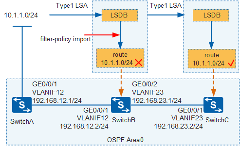
In Figure 6, three switches belong to OSPF Area 0. SwitchA advertises the test network segment 10.1.1.0/24. It is required that the filter-policy import command be configured on SwitchB so that the IP routing table of SwitchB does not contain the route 10.1.1.0/24.
Configuration
Define an IP prefix list on SwitchB to filter routes as required.
[SwitchB] ip ip-prefix huawei index 10 deny 10.1.1.0 24           //Deny this route.
[SwitchB] ip ip-prefix huawei index 20 permit 0.0.0.0 0 less-equal 32     //Permit all routes.
Configure the filter-policy import command in the OSPF view of SwitchB.
[SwitchB] ospf
[SwitchB-ospf-1] filter-policy ip-prefix huawei import
Verification
After the preceding configurations are complete, check the IP routing tables of SwitchB and SwitchC.
[SwitchB] display ip routing-table
Route Flags: R - relay, D - download to fib, T - to vpn-instance
-----------------------------------------------------------------------------
Routing Tables: Public
         Destinations : 6        Routes : 6

Destination/Mask    Proto   Pre  Cost      Flags NextHop         Interface

      127.0.0.0/8   Direct  0    0           D   127.0.0.1       InLoopBack0
      127.0.0.1/32  Direct  0    0           D   127.0.0.1       InLoopBack0
   192.168.12.0/24  Direct  0    0           D   192.168.12.2    Vlanif12
   192.168.12.2/32  Direct  0    0           D   127.0.0.1       Vlanif12
   192.168.23.0/24  Direct  0    0           D   192.168.23.1    Vlanif23
   192.168.23.1/32  Direct  0    0           D   127.0.0.1       Vlanif23
[SwitchC] display ip routing-table
Route Flags: R - relay, D - download to fib, T - to vpn-instance
------------------------------------------------------------------------------
Routing Tables: Public
         Destinations : 6        Routes : 6

Destination/Mask    Proto   Pre  Cost      Flags NextHop         Interface

       10.1.1.0/24  OSPF    10   3           D   192.168.23.1    Vlanif23
      127.0.0.0/8   Direct  0    0           D   127.0.0.1       InLoopBack0
      127.0.0.1/32  Direct  0    0           D   127.0.0.1       InLoopBack0
   192.168.12.0/24  OSPF    10   2           D   192.168.23.1    Vlanif23
   192.168.23.0/24  Direct  0    0           D   192.168.23.2    Vlanif23
   192.168.23.2/32  Direct  0    0           D   127.0.0.1       Vlanif23
The preceding command output shows that, although the route 10.1.1.0/24 has been filtered out on SwitchB, its LSA is still transmitted to SwitchC, so the IP routing table of SwitchC still contains this route. This result also confirms that in link-state routing protocols, a filter-policy filters only routing information but not LSAs.
The LSDBs of SwitchB and SwitchC still contain the LSA describing the route 10.1.1.0/24. To verify this, check LSA information on SwitchB and SwitchC.
[SwitchB] display ospf lsdb router

   OSPF Process 1 with Router ID 10.10.10.2
              Area: 0.0.0.0
      Link State Database
………

  Type      : Router
  Ls id     : 10.10.10.1
  Adv rtr   : 10.10.10.1
  Ls age    : 139
  Len       : 48
  Options   :  E
  seq#      : 80000005
  chksum    : 0x41c4
  Link count: 2
   * Link ID: 10.1.1.0
     Data   : 255.255.255.0
     Link Type: StubNet
     Metric : 1
     Priority : Low
   * Link ID: 192.168.12.2
     Data   : 192.168.12.1
     Link Type: TransNet
     Metric : 1
[SwitchC] display  ospf lsdb  router

   OSPF Process 1 with Router ID 10.10.10.3
             Area: 0.0.0.0
     Link State Database
…………

  Type      : Router
  Ls id     : 10.10.10.1
  Adv rtr   : 10.10.10.1
  Ls age    : 81
  Len       : 48
  Options   :  E
  seq#      : 80000005
  chksum    : 0x41c4
  Link count: 2
   * Link ID: 10.1.1.0
     Data   : 255.255.255.0
     Link Type: StubNet
     Metric : 1
     Priority : Low
   * Link ID: 192.168.12.2
     Data   : 192.168.12.1
     Link Type: TransNet
     Metric : 1
The preceding command output shows that the LSDBs of SwitchB and SwitchC still contain the LSA describing the route 10.1.1.0/24.
Using a Filter-Policy to Filter the Inter-Area Routes Received by OSPF
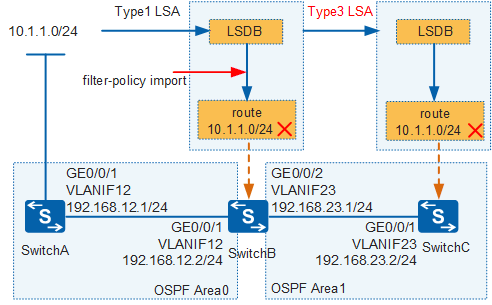
In Figure 7 there are two OSPF areas, Area 0 and Area 1. SwitchB and SwitchC transmit Type 3 LSAs, which are generated by SwitchB to describe inter-area routes. The configuration is similar to the configuration in the previous scenario. The following describes the filtering result.
Before configuring a filter-policy, check the IP routing tables of SwitchB and SwitchC.
[SwitchB] display ip routing-table
Route Flags: R - relay, D - download to fib, T - to vpn-instance
-----------------------------------------------------------------------------
Routing Tables: Public
         Destinations : 7        Routes : 7

Destination/Mask    Proto   Pre  Cost      Flags NextHop         Interface

       10.1.1.0/24  OSPF    10   2           D   192.168.12.1    Vlanif12
      127.0.0.0/8   Direct  0    0           D   127.0.0.1       InLoopBack0
      127.0.0.1/32  Direct  0    0           D   127.0.0.1       InLoopBack0
   192.168.12.0/24  Direct  0    0           D   192.168.12.2    Vlanif12
   192.168.12.2/32  Direct  0    0           D   127.0.0.1       Vlanif12
   192.168.23.0/24  Direct  0    0           D   192.168.23.1    Vlanif23
   192.168.23.1/32  Direct  0    0           D   127.0.0.1       Vlanif23
[SwitchC] display ip routing-table
Route Flags: R - relay, D - download to fib, T - to vpn-instance
-----------------------------------------------------------------------------
Routing Tables: Public
         Destinations : 6        Routes : 6

Destination/Mask    Proto   Pre  Cost      Flags NextHop         Interface

       10.1.1.0/24  OSPF    10   3           D   192.168.23.1    Vlanif23
      127.0.0.0/8   Direct  0    0           D   127.0.0.1       InLoopBack0
      127.0.0.1/32  Direct  0    0           D   127.0.0.1       InLoopBack0
   192.168.12.0/24  OSPF    10   2           D   192.168.23.1    Vlanif23
   192.168.23.0/24  Direct  0    0           D   192.168.23.2    Vlanif23
   192.168.23.2/32  Direct  0    0           D   127.0.0.1       Vlanif23
The preceding command output shows that before a filter-policy is configured, the IP routing tables of SwitchB and SwitchC contain the route 10.1.1.0/24.
Verification
After the filter-policy import command is configured on SwitchB, check the IP routing tables of SwitchB and SwitchC.
[SwitchB] display  ip routing-table
Route Flags: R - relay, D - download to fib, T - to vpn-instance
-----------------------------------------------------------------------------
Routing Tables: Public
         Destinations : 6        Routes : 6

Destination/Mask    Proto   Pre  Cost      Flags NextHop         Interface

      127.0.0.0/8   Direct  0    0           D   127.0.0.1       InLoopBack0
      127.0.0.1/32  Direct  0    0           D   127.0.0.1       InLoopBack0
   192.168.12.0/24  Direct  0    0           D   192.168.12.2    Vlanif12
   192.168.12.2/32  Direct  0    0           D   127.0.0.1       Vlanif12
   192.168.23.0/24  Direct  0    0           D   192.168.23.1    Vlanif23
   192.168.23.1/32  Direct  0    0           D   127.0.0.1       Vlanif23
[SwitchC] display ip routing-table
Route Flags: R - relay, D - download to fib, T - to vpn-instance
------------------------------------------------------------------------------
Routing Tables: Public
         Destinations : 5        Routes : 5

Destination/Mask    Proto   Pre  Cost      Flags NextHop         Interface

      127.0.0.0/8   Direct  0    0           D   127.0.0.1       InLoopBack0
      127.0.0.1/32  Direct  0    0           D   127.0.0.1       InLoopBack0
   192.168.12.0/24  OSPF    10   2           D   192.168.23.1    Vlanif23
   192.168.23.0/24  Direct  0    0           D   192.168.23.2    Vlanif23
   192.168.23.2/32  Direct  0    0           D   127.0.0.1       Vlanif23
There are two OSPF areas. The route 10.1.1.0/24 on SwitchC is described by the Type 3 LSA generated by SwitchB, but this route has been filtered out by SwitchB. Therefore, the Type 3 LSA describing an inter-area route cannot be generated, and SwitchC cannot learn the route 10.1.1.0/24 again.