Example for Configuring the Device as a DHCP Server (Based on the Interface Address Pool)
DHCP Server Overview
Users require that all terminals on a network dynamically obtain network parameters such as IP addresses, DNS server IP address, routing information, and gateway information. The users do not need to manually configure the network parameters including terminal IP addresses. In addition, some mobile terminals (for example, mobile phones, tablets, and laptops) should support plug-and-play, without modification on network parameters each time. To meet these requirements, the DHCP server function can be configured on an aggregation-layer user gateway or a core-layer device to assign network parameters such as IP addresses to terminals.
The Dynamic Host Configuration Protocol (DHCP) uses the client/server mode to dynamically configure and uniformly manage network parameters for users. The DHCP server uses an address pool to assign network parameters such as IP addresses to the users. The global address pool or an interface address pool can be used.
The configuration of an interface address pool is simple, which can be used only when the users and DHCP server belong to the same network segment and the server can only assign network parameters to the users on the interface. It is applicable to small networks with a limited number of devices and controllable configuration and maintenance workload. After the DHCP server function based on the interface address pool is configured on the user gateway, the hosts and mobile terminals on the interface can automatically obtain network parameters such as IP addresses, without manual configuration and modification.
Compared with an interface address pool, the global address pool can be applied to large networks. The DHCP server function based on the global address pool should be configured on a core device, or an exclusive DHCP server be used to assign network parameters such as IP addresses. The user gateway only needs to be enabled with the DHCP relay function. For details, see Example for Configuring the Device as a DHCP Relay (on the Same Network).
Configuration Notes
For applicable product models and versions, see Applicable Product Models and Versions.

For details about software mappings, visit Hardware Query Tool and search for the desired product model.
Networking Requirements
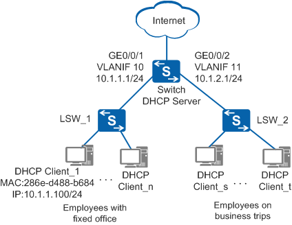
As shown in Figure 1, an enterprise divides two network segments for office terminals: 10.1.1.0/24 for employees with fixed office terminals and 10.1.2.0/24 for employees on business trips to temporarily access the network. The enterprise requires that DHCP be used to assign IP addresses to employees with fixed office terminals and employees on business trips. A PC (DHCP Client_1) requires fixed IP address 10.1.1.100/24 to meet service requirements.
Configuration Roadmap
The configuration roadmap is as follows:
Configure the DHCP server function on the Switch to dynamically assign IP addresses to the terminals on the two network segments. Configure the IP address lease to 30 days for the employees with fixed office terminals on 10.1.1.0/24 and one day for the employees on business trips on 10.1.2.0/24 to temporarily access the network.
Configure the interface link types and VLANs on LSW_1 and LSW_2 to implement Layer 2 communication.
Procedure
- Enable the DHCP service. By default, the service is disabled.
<HUAWEI> system-view
[HUAWEI] sysname Switch
[Switch] dhcp enable
- Add interfaces to VLANs.
# Add GE0/0/1 to VLAN 10.
[Switch] vlan batch 10 to 11
[Switch] interface gigabitethernet 0/0/1
[Switch-GigabitEthernet0/0/1] port link-type access
[Switch-GigabitEthernet0/0/1] port default vlan 10
[Switch-GigabitEthernet0/0/1] quit
# Add GE0/0/2 to VLAN 11.
[Switch] interface gigabitethernet 0/0/2
[Switch-GigabitEthernet0/0/2] port link-type access
[Switch-GigabitEthernet0/0/2] port default vlan 11
[Switch-GigabitEthernet0/0/2] quit
- Configure IP addresses for VLANIF interfaces.
# Configure an IP address for VLANIF 10.
[Switch] interface vlanif 10
[Switch-Vlanif10] ip address 10.1.1.1 24  //Network segment assigned by the enterprise for fixed office terminals
[Switch-Vlanif10] quit
# Configure an IP address for VLANIF 11.
[Switch] interface vlanif 11 [Switch-Vlanif11] ip address 10.1.2.1 24 //Network segment assigned by the enterprise for employees on business trips [Switch-Vlanif11] quit - Configure an interface address pool.
# Configure the terminals connected to VLANIF 10 to obtain IP addresses from the interface address pool.
[Switch] interface vlanif 10
[Switch-Vlanif10] dhcp select interface  //Enable the DHCP server function based on the interface address pool on the interface. By default, the function is disabled.
[Switch-Vlanif10] dhcp server lease day 30  //The default lease is one day. Modify the lease to 30 days.
[Switch-Vlanif10] dhcp server static-bind ip-address 10.1.1.100 mac-address 286e-d488-b684  //Allocate a fixed IP address to Client_1.
[Switch-Vlanif10] quit
# Configure the terminals connected to VLANIF 11 to obtain IP addresses from the interface address pool. The default lease (one day) is used and does not need to be configured.
[Switch] interface vlanif 11 [Switch-Vlanif11] dhcp select interface //Enable the DHCP server function based on the interface address pool on the interface. By default, the function is disabled. [Switch-Vlanif11] quit - Enable the device to save DHCP data to the storage device. If a fault occurs on the device, you can run the dhcp server database recover command after the system restarts to restore DHCP data from files on the storage device.
[Switch] dhcp server database enable
- Configure each terminal (using the PC running Windows 7 as an example) to automatically obtain an IP address.
- Right-click Network and choose Properties to display the Network and Sharing Center window.
- Click Local Area Connection to display the Local Area Connection Status window.
- Click Properties to display the Local Area Connection Properties window.
- Select Internet Protocol Version 4 (TCP/IPv4) and click Properties to display the Internet Protocol Version 4 (TCP/IPv4) Properties window. Select Obtain an IP address automatically, and click OK.
- Verify the configuration.
Run the display ip pool command on the Switch to check the configuration of VLANIF 10 and VLANIF 11. For example, the enterprise has 100 employees with fixed office terminals and 3 employees on business trips.
[Switch] display ip pool interface vlanif10
  Pool-name        : Vlanif10
  Pool-No          : 0
  Lease            : 30 Days 0 Hours 0 Minutes
  Domain-name      : -
  DNS-server0      : -
  NBNS-server0     : -
  Netbios-type     : -
  Position         : Interface       Status             : Unlocked
  Gateway-0        : 10.1.1.1
  Network          : 10.1.1.0
  Mask             : 255.255.255.0
  VPN instance     : --
  Logging          : Disable
  Conflicted address recycle interval: -
  Address Statistic: Total       :253       Used        :100
                     Idle        :153       Expired     :0
                     Conflict    :0         Disable     :0

 -------------------------------------------------------------------------------
  Network section
         Start           End       Total    Used Idle(Expired) Conflict Disabled
 -------------------------------------------------------------------------------
        10.1.1.1      10.1.1.254     253     100        153(0)       0     0
 -------------------------------------------------------------------------------
[Switch] display ip pool interface vlanif11 Pool-name : Vlanif11 Pool-No : 1 Lease : 1 Days 0 Hours 0 Minutes Domain-name : - DNS-server0 : - NBNS-server0 : - Netbios-type : - Position : Interface Status : Unlocked Gateway-0 : 10.1.2.1 Network : 10.1.2.0 Mask : 255.255.255.0 VPN instance : -- Logging : Disable Conflicted address recycle interval: - Address Statistic: Total :253 Used :3 Idle :250 Expired :0 Conflict :0 Disable :0 ------------------------------------------------------------------------------- Network section Start End Total Used Idle(Expired) Conflict Disabled ------------------------------------------------------------------------------- 10.1.2.1 10.1.2.254 253 3 250(0) 0 0 -------------------------------------------------------------------------------Check IP address information on Client_1 (using Windows 7 operating system). The IP address 10.1.1.100/24 has been assigned to Client_1.
C:\Documents and Settings\Administrator>ipconfig

Windows IP Configuration


Ethernet adapter Local Area Connection 2:

   Connection-specific DNS Suffix  . :
   IPv4 Address. . . . . . . . . . . : 10.1.1.100
   Subnet Mask . . . . . . . . . . . : 255.255.254.0
   Default Gateway . . . . . . . . . : 10.1.1.1
Check IP address information another DHCP client (for example, a terminal belonging to the network segment 10.1.1.0/24 and using Windows 7 operating system). An IP address has been assigned.
C:\Documents and Settings\Administrator>ipconfig

Windows IP Configuration


Ethernet adapter Local Area Connection 2:

   Connection-specific DNS Suffix  . :
   IPv4 Address. . . . . . . . . . . : 10.1.1.51
   Subnet Mask . . . . . . . . . . . : 255.255.254.0
   Default Gateway . . . . . . . . . : 10.1.1.1
Configuration Files
Configuration file of the Switch
#
sysname Switch
#
vlan batch 10 to 11
#
dhcp enable
#
dhcp server database enable
#
interface Vlanif10
 ip address 10.1.1.1 255.255.255.0
 dhcp select interface
 dhcp server static-bind ip-address 10.1.1.100 mac-address 286e-d488-b684
 dhcp server lease day 30 hour 0 minute 0
#
interface Vlanif11
 ip address 10.1.2.1 255.255.255.0
 dhcp select interface
#
interface GigabitEthernet0/0/1
 port link-type access
 port default vlan 10
#
interface GigabitEthernet0/0/2
 port link-type access
 port default vlan 11
#
return
Applicable Product Models and Versions
Series |
Product Model |
Software Version |
|---|---|---|
S2700 |
S2720-EI |
V200R009C00, V200R010C00, V200R011C10, V200R012C00, V200R013C00, V200R019C00, V200R019C10 |
S2750-EI |
V200R005C00SPC300, V200R006C00, V200R007C00, V200R008C00, V200R009C00, V200R010C00, V200R011C00, V200R011C10, V200R012C00 |
|
S3700 |
S3700-SI, S3700-EI |
V100R006C05 |
S3700-HI |
V200R001C00 |
|
S5700 |
S5700-LI |
V200R005C00SPC300, V200R006C00, V200R007C00, V200R008C00, V200R009C00, V200R010C00, V200R011C00, V200R011C10, V200R012C00 |
S5700S-LI |
V200R005C00SPC300, V200R006C00, V200R007C00, V200R008C00, V200R009C00, V200R010C00, V200R011C00, V200R011C10, V200R012C00 |
|
S5700-SI |
V200R001C00, V200R002C00, V200R003C00, V200R005C00 |
|
S5700-EI |
V200R001(C00&C01), V200R002C00, V200R003C00, V200R005(C00&C01&C02&C03) |
|
S5700-HI |
V200R001(C00&C01), V200R002C00, V200R003C00, V200R005(C00SPC500&C01&C02) |
|
S5710-X-LI |
V200R008C00, V200R009C00, V200R010C00, V200R011C00, V200R011C10, V200R012C00 |
|
S5710-EI |
V200R001C00, V200R002C00, V200R003C00, V200R005(C00&C02) |
|
S5710-HI |
V200R003C00, V200R005(C00&C02&C03) |
|
S5720-LI, S5720S-LI |
V200R010C00, V200R011C00, V200R011C10, V200R012(C00&C20), V200R013C00, V200R019C00, V200R019C10 |
|
S5720-SI, S5720S-SI |
V200R008C00, V200R009C00, V200R010C00, V200R011C00, V200R011C10, V200R012C00, V200R013C00, V200R019C00, V200R019C10 |
|
S5720I-SI |
V200R012C00, V200R013C00, V200R019C00, V200R019C10 |
|
S5720-EI |
V200R007C00, V200R008C00, V200R009C00, V200R010C00, V200R011C00, V200R011C10, V200R012C00, V200R013C00, V200R019C00, V200R019C10 |
|
S5720-HI |
V200R006C00, V200R007(C00&C10), V200R008C00, V200R009C00, V200R010C00, V200R011C00, V200R011C10, V200R012C00, V200R013C00, V200R019C00, V200R019C10 |
|
S5730-HI |
V200R012C00, V200R013C00, V200R019C00, V200R019C10 |
|
S5730-SI |
V200R011C10, V200R012C00, V200R013C00, V200R019C00, V200R019C10 |
|
S5730S-EI |
V200R011C10, V200R012C00, V200R013C00, V200R019C00, V200R019C10 |
|
S5731-H |
V200R013C02, V200R019C00, V200R019C10 |
|
S5731-S, S5731S-S |
V200R019C00, V200R019C10 |
|
S5731S-H |
V200R019C00, V200R019C10 |
|
S5732-H |
V200R019C00, V200R019C10 |
|
S5735-L, S5735S-L |
V200R019C00, V200R019C10 |
|
S5735S-L-M |
V200R019C00, V200R019C10 |
|
S5735-S, S5735S-S |
V200R019C00, V200R019C10 |
|
S5700 |
S5735-S-I |
V200R019C10 |
S6700 |
S6700-EI |
V200R001(C00&C01), V200R002C00, V200R003C00, V200R005(C00&C01&C02) |
S6720-LI, S6720S-LI |
V200R011C00, V200R011C10, V200R012C00, V200R013C00, V200R019C00, V200R019C10 |
|
S6720-SI, S6720S-SI |
V200R011C00, V200R011C10, V200R012C00, V200R013C00, V200R019C00, V200R019C10 |
|
S6720-EI |
V200R008C00, V200R009C00, V200R010C00, V200R011C00, V200R011C10, V200R012C00, V200R013C00, V200R019C00, V200R019C10 |
|
S6720S-EI |
V200R009C00, V200R010C00, V200R011C00, V200R011C10, V200R012C00, V200R013C00, V200R019C00, V200R019C10 |
|
S6720-HI |
V200R012C00, V200R013C00, V200R019C00, V200R019C10 |
|
S6730-H |
V200R013C02, V200R019C00, V200R019C10 |
|
S6730-S, S6730S-S |
V200R019C00, V200R019C10 |
|
S6730S-H |
V200R019C10 |
|
S7700 |
S7703, S7706, S7712 |
V200R001(C00&C01), V200R002C00, V200R003C00, V200R005C00, V200R006C00, V200R007C00, V200R008C00, V200R009C00, V200R010C00, V200R011C10, V200R012C00, V200R013C00, V200R013C02, V200R019C00, V200R019C10 |
S7703 PoE |
V200R013C00, V200R019C00, V200R019C10 |
|
S7706 PoE |
V200R013C00, V200R019C00, V200R019C10 |
|
S9700 |
S9703, S9706, S9712 |
V200R001(C00&C01), V200R002C00, V200R003C00, V200R005C00, V200R006C00, V200R007(C00&C10), V200R008C00, V200R009C00, V200R010C00, V200R011C10, V200R012C00, V200R013C00 |