Example for Configuring the Device as a DHCP Relay (Across a GRE Tunnel)
DHCP Relay Overview
A DHCP relay forwards DHCP packets between the DHCP server and clients. When the DHCP server and clients belong to different network segment, the DHCP relay needs to be configured. For DHCP clients, the DHCP relay is the DHCP server; for the DHCP server, the DHCP relay is a DHCP client.
The DHCP relay function applies to large networks with many sparsely-distributed user gateways. To reduce the maintenance workload, the network administrator does not want to configure the DHCP server function on each aggregation switch (user gateway) and requires that the DHCP server function be configured on a core device or an exclusive DHCP server be deployed in the server area. In this case, the aggregation switches functioning as the user gateways need to be configured with the DHCP relay function to implement exchange of DHCP packets between the DHCP server and clients.
The DHCP relay and DHCP server can be deployed across a VPN (such as GRE or MPLS L3VPN) network. A GRE tunnel is used as an example to describe how to configure a DHCP relay.
Configuration Notes
For applicable product models and versions, see Applicable Product Models and Versions.

For details about software mappings, visit Hardware Query Tool and search for the desired product model.
Networking Requirements
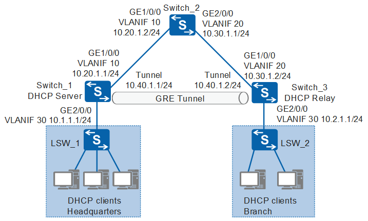
As shown in Figure 1, an enterprise deploys its headquarters and branch in different areas. A GRE tunnel is deployed between the headquarters and branch to enable them to communicate. To facilitate unified management, the enterprise administrator deploys the DHCP server on Switch_1 in the headquarters to assign IP addresses to the terminals in the headquarters and branch. The network segments 10.1.1.0/24 and 10.2.1.0/24 are planned for the headquarters and branch respectively.
Configuration Roadmap
The configuration roadmap is as follows:
Run OSPF between Switch_1, Switch_2, and Switch_3 to ensure the communication between devices.
On Switch_1 and Switch_3, configure tunnel interfaces and create a GRE tunnel.
On Switch_1, configure the DHCP server based on the global address pool so that the DHCP server can assign IP addresses from the global address pool to the terminals in the headquarters and branch.
On Switch_3, configure the DHCP relay function to function as the branch's gateway to forward DHCP packets between the terminals and DHCP servers so that the terminals can apply to the DHCP server for IP addresses.
Use a Huawei S series switch as an example for the DHCP server (Switch_1).
Configure the interface link types and VLANs on LSW_1 and LSW_2 to implement Layer 2 communication.
Procedure
- Configure an IP address for each physical interface on Switch_1 through Switch_3.
# Configure Switch_1.
<HUAWEI> system-view
[HUAWEI] sysname Switch_1
[Switch_1] vlan batch 10 30
[Switch_1] interface gigabitethernet 1/0/0
[Switch_1-GigabitEthernet1/0/0] port link-type trunk
[Switch_1-GigabitEthernet1/0/0] port trunk allow-pass vlan 10
[Switch_1-GigabitEthernet1/0/0] quit
[Switch_1] interface gigabitethernet 2/0/0
[Switch_1-GigabitEthernet2/0/0] port link-type trunk
[Switch_1-GigabitEthernet2/0/0] port trunk allow-pass vlan 30
[Switch_1-GigabitEthernet2/0/0] quit
[Switch_1] interface vlanif 10
[Switch_1-Vlanif10] ip address 10.20.1.1 24
[Switch_1-Vlanif10] quit
[Switch_1] interface vlanif 30
[Switch_1-Vlanif30] ip address 10.1.1.1 24
[Switch_1-Vlanif30] quit
# Configure Switch_2.
<HUAWEI> system-view
[HUAWEI] sysname Switch_2
[Switch_2] vlan batch 10 20
[Switch_2] interface gigabitethernet 1/0/0
[Switch_2-GigabitEthernet1/0/0] port link-type trunk
[Switch_2-GigabitEthernet1/0/0] port trunk allow-pass vlan 10
[Switch_2-GigabitEthernet1/0/0] quit
[Switch_2] interface gigabitethernet 2/0/0
[Switch_2-GigabitEthernet2/0/0] port link-type trunk
[Switch_2-GigabitEthernet2/0/0] port trunk allow-pass vlan 20
[Switch_2-GigabitEthernet2/0/0] quit
[Switch_2] interface vlanif 10
[Switch_2-Vlanif10] ip address 10.20.1.2 24
[Switch_2-Vlanif10] quit
[Switch_2] interface vlanif 20
[Switch_2-Vlanif20] ip address 10.30.1.1 24
[Switch_2-Vlanif20] quit
# Configure Switch_3.
<HUAWEI> system-view
[HUAWEI] sysname Switch_3
[Switch_3] vlan batch 20 30
[Switch_3] interface gigabitethernet 1/0/0
[Switch_3-GigabitEthernet1/0/0] port link-type trunk
[Switch_3-GigabitEthernet1/0/0] port trunk allow-pass vlan 20
[Switch_3-GigabitEthernet1/0/0] quit
[Switch_3] interface gigabitethernet 2/0/0
[Switch_3-GigabitEthernet2/0/0] port link-type trunk
[Switch_3-GigabitEthernet2/0/0] port trunk allow-pass vlan 30
[Switch_3-GigabitEthernet2/0/0] quit
[Switch_3] interface vlanif 20
[Switch_3-Vlanif20] ip address 10.30.1.2 24
[Switch_3-Vlanif20] quit
[Switch_3] interface vlanif 30
[Switch_3-Vlanif30] ip address 10.2.1.1 24
[Switch_3-Vlanif30] quit
- Run OSPF between Switch_1, Switch_2, and Switch_3.
# Configure Switch_1.
[Switch_1] ospf 1
[Switch_1-ospf-1] area 0
[Switch_1-ospf-1-area-0.0.0.0] network 10.20.1.0 0.0.0.255
[Switch_1-ospf-1-area-0.0.0.0] quit
[Switch_1-ospf-1] quit
# Configure Switch_2.
[Switch_2] ospf 1
[Switch_2-ospf-1] area 0
[Switch_2-ospf-1-area-0.0.0.0] network 10.20.1.0 0.0.0.255
[Switch_2-ospf-1-area-0.0.0.0] network 10.30.1.0 0.0.0.255
[Switch_2-ospf-1-area-0.0.0.0] quit
[Switch_2-ospf-1] quit
# Configure Switch_3.
[Switch_3] ospf 1
[Switch_3-ospf-1] area 0
[Switch_3-ospf-1-area-0.0.0.0] network 10.30.1.0 0.0.0.255
[Switch_3-ospf-1-area-0.0.0.0] quit
[Switch_3-ospf-1] quit
- Configure static routes.# Configure a static route to the network segment on Switch_1.
[Switch_1] ip route-static 10.2.1.0 255.255.255.0 tunnel 1# Configure a static route to the server segment on Switch_3.[Switch_3] ip route-static 10.1.1.0 255.255.255.0 tunnel 1 - Configure tunnel interfaces.
# Configure Switch_1.
[Switch_1] interface tunnel 1
[Switch_1-Tunnel1] tunnel-protocol gre
[Switch_1-Tunnel1] ip address 10.40.1.1 24
[Switch_1-Tunnel1] source 10.20.1.1
[Switch_1-Tunnel1] destination 10.30.1.2
[Switch_1-Tunnel1] quit
# Configure Switch_3.
[Switch_3] interface tunnel 1
[Switch_3-Tunnel1] tunnel-protocol gre
[Switch_3-Tunnel1] ip address 10.40.1.2 24
[Switch_3-Tunnel1] source 10.30.1.2
[Switch_3-Tunnel1] destination 10.20.1.1
[Switch_3-Tunnel1] quit
- Configure the DHCP server function on Switch_1.
# Enable the DHCP service. By default, the service is disabled.
[Switch_1] dhcp enable
# Create a global address pool and configure related parameters.
[Switch_1] ip pool pool1
[Switch_1-ip-pool-pool1] network 10.2.1.0 mask 255.255.255.0  //Network segment for terminals in the branch
[Switch_1-ip-pool-pool1] gateway-list 10.2.1.1  //Gateway address for terminals in the branch
[Switch_1-ip-pool-pool1] quit
[Switch_1] ip pool pool2
[Switch_1-ip-pool-pool2] network 10.1.1.0 mask 255.255.255.0  //Network segment for terminals in the headquarters
[Switch_1-ip-pool-pool2] gateway-list 10.1.1.1  //Gateway address for terminals in the headquarters
[Switch_1-ip-pool-pool2] quit
# Configure the terminals connected to VLANIF30 to obtain IP addresses from the global address pool.[Switch_1] interface vlanif 30 [Switch_1-Vlanif30] dhcp select global //Enable the DHCP server function based on the global address pool on the interface. By default, the function is disabled. [Switch_1-Vlanif30] quit - # Configure the DHCP relay function on Switch_3.
# Enable the DHCP service. By default, the service is disabled.
[Switch_3] dhcp enable
# Configure the DHCP relay function on VLANIF 30 and specifies the DHCP server address for the relay.[Switch_3] interface vlanif 30 [Switch_3-Vlanif30] dhcp select relay //Enable the DHCP relay function. By default, the function is disabled. [Switch_3-Vlanif30] dhcp relay server-ip 10.1.1.1 //Configure the DHCP server IP address for the DHCP relay agent. [Switch_3-Vlanif30] quit
- Configure each terminal (using the PC running Windows 7 as an example) to automatically obtain an IP address.
- Right-click Network and choose Properties to display the Network and Sharing Center window.
- Click Local Area Connection to display the Local Area Connection Status window.
- Click Properties to display the Local Area Connection Properties window.
- Select Internet Protocol Version 4 (TCP/IPv4) and click Properties to display the Internet Protocol Version 4 (TCP/IPv4) Properties window. Select Obtain an IP address automatically, and click OK.
- Verify the configuration. The following uses the command output in V200R010C00 as an example.
# Run the display dhcp relay interface vlanif 30 command on Switch_3 to check the DHCP relay configuration.
[Switch_3] display dhcp relay interface vlanif 30
 DHCP relay agent running information of interface Vlanif30 :
 Server IP address [00] : 10.1.1.1
 Gateway address in use : 10.2.1.1
# Run the display ip pool command on Switch_1 to check the IP address allocation of pool1 and pool2. For example, the headquarters has 100 terminals and the branch has 50 terminals.
[Switch_1] display ip pool name pool1
  Pool-name        : pool1
  Pool-No          : 0
  Lease            : 1 Days 0 Hours 0 Minutes
  Domain-name      : -
  DNS-server0      : -
  NBNS-server0     : -
  Netbios-type     : -
  Position         : Local           Status             : Unlocked
  Gateway-0        : 10.2.1.1
  Network          : 10.2.1.0
  Mask             : 255.255.255.0
  VPN instance     : --
  Logging          : Disable
  Conflicted address recycle interval: -
  Address Statistic: Total       :253       Used        :50
  Idle        :203       Expired     :0
  Conflict    :0         Disable     :0

 -------------------------------------------------------------------------------
  Network section
         Start           End       Total    Used Idle(Expired) Conflict Disabled
 -------------------------------------------------------------------------------
        10.2.1.1      10.2.1.254     253      50        203(0)       0     0
 -------------------------------------------------------------------------------
[Switch_1] display ip pool name pool2 Pool-name : pool2 Pool-No : 1 Lease : 1 Days 0 Hours 0 Minutes Domain-name : - DNS-server0 : - NBNS-server0 : - Netbios-type : - Position : Local Status : Unlocked Gateway-0 : 10.1.1.1 Network : 10.1.1.0 Mask : 255.255.255.0 VPN instance : -- Logging : Disable Conflicted address recycle interval: - Address Statistic: Total :253 Used :50 Idle :203 Expired :0 Conflict :0 Disable :0 ------------------------------------------------------------------------------- Network section Start End Total Used Idle(Expired) Conflict Disabled ------------------------------------------------------------------------------- 10.1.1.1 10.1.1.254 253 100 153(0) 0 0 -------------------------------------------------------------------------------
Configuration Files
Configuration file of Switch_1
#
sysname Switch_1
#
vlan batch 10 30
#
dhcp enable
#
ip pool pool1
 gateway-list 10.2.1.1
 network 10.2.1.0 mask 255.255.255.0
#
ip pool pool2
 gateway-list 10.1.1.1
 network 10.1.1.0 mask 255.255.255.0
#
interface Vlanif10
 ip address 10.20.1.1 255.255.255.0
#
interface Vlanif30
 ip address 10.1.1.1 255.255.255.0
 dhcp select global
#
interface GigabitEthernet1/0/0
 port link-type trunk
 port trunk allow-pass vlan 10
#
interface GigabitEthernet2/0/0
 port link-type trunk
 port trunk allow-pass vlan 30
#
interface Tunnel1
 ip address 10.40.1.1 255.255.255.0
 tunnel-protocol gre
 source 10.20.1.1
 destination 10.30.1.2
#
ospf 1
 area 0.0.0.0
  network 10.20.1.0 0.0.0.255
#
ip route-static 10.2.1.0 255.255.255.0 Tunnel1
#
return
Configuration file of Switch_2
#
sysname Switch_2
#
vlan batch 10 20
#
interface Vlanif10
 ip address 10.20.1.2 255.255.255.0
#
interface Vlanif20
 ip address 10.30.1.1 255.255.255.0
#
interface GigabitEthernet1/0/0
 port link-type trunk
 port trunk allow-pass vlan 10
#
interface GigabitEthernet2/0/0
 port link-type trunk
 port trunk allow-pass vlan 20
#
ospf 1
 area 0.0.0.0
  network 10.20.1.0 0.0.0.255
  network 10.30.1.0 0.0.0.255
#
return
Configuration file of Switch_3
#
sysname Switch_3
#
vlan batch 20 30
#
dhcp enable
#
interface Vlanif20
 ip address 10.30.1.2 255.255.255.0
#
interface Vlanif30
 ip address 10.2.1.1 255.255.255.0
 dhcp select relay
 dhcp relay server-ip 10.1.1.1
#
interface GigabitEthernet1/0/0
 port link-type trunk
 port trunk allow-pass vlan 20
#
interface GigabitEthernet2/0/0
 port link-type trunk
 port trunk allow-pass vlan 30
#
interface Tunnel1
 ip address 10.40.1.2 255.255.255.0
 tunnel-protocol gre
 source 10.30.1.2
 destination 10.20.1.1
#
ospf 1
 area 0.0.0.0
  network 10.30.1.0 0.0.0.255
#
ip route-static 10.1.1.0 255.255.255.0 Tunnel1
#
return
Applicable Product Models and Versions
Series |
Product Model |
Software Version |
|---|---|---|
S5700 |
S5710-EI |
V200R001C00, V200R002C00, V200R003C00, V200R005(C00&C02) |
S5720-EI |
V200R007C00, V200R008C00, V200R009C00, V200R010C00, V200R011C00, V200R011C10, V200R012C00, V200R013C00, V200R019C00, V200R019C10 |
|
S5700-HI |
V200R001(C00&C01), V200R002C00, V200R003C00, V200R005(C00SPC500&C01&C02) |
|
S5710-HI |
V200R003C00, V200R005(C00&C02&C03) |
|
S5720-HI |
V200R006C00, V200R007(C00&C10), V200R008C00, V200R009C00, V200R010C00, V200R011C00, V200R011C10, V200R012C00, V200R013C00, V200R019C00, V200R019C10 |
|
S5730-HI |
V200R012C00, V200R013C00, V200R019C00, V200R019C10 |
|
S5731-H |
V200R013C02, V200R019C00, V200R019C10 |
|
S5731-S, S5731S-S |
V200R019C00, V200R019C10 |
|
S5731S-H |
V200R019C00, V200R019C10 |
|
S5732-H |
V200R019C00, V200R019C10 |
|
S5735-L, S5735S-L |
V200R019C00, V200R019C10 |
|
S5735S-L-M |
V200R019C00, V200R019C10 |
|
S5735-S, S5735S-S |
V200R019C00, V200R019C10 |
|
S5700 |
S5735-S-I |
V200R019C10 |
S6700 |
S6700-EI |
V200R001(C00&C01), V200R002C00, V200R003C00, V200R005(C00&C01&C02) |
S6720-EI |
V200R008C00, V200R009C00, V200R010C00, V200R011C00, V200R011C10, V200R012C00, V200R013C00, V200R019C00, V200R019C10 |
|
S6720S-EI |
V200R009C00, V200R010C00, V200R011C00, V200R011C10, V200R012C00, V200R013C00, V200R019C00, V200R019C10 |
|
S6720-HI |
V200R012C00, V200R013C00, V200R019C00, V200R019C10 |
|
S6730-H |
V200R013C02, V200R019C00, V200R019C10 |
|
S6730-S, S6730S-S |
V200R019C00, V200R019C10 |
|
S6730S-H |
V200R019C10 |
|
S7700 |
S7703, S7706, S7712 |
V200R001(C00&C01), V200R002C00, V200R003C00, V200R005C00, V200R006C00, V200R007C00, V200R008C00, V200R009C00, V200R010C00, V200R011C10, V200R012C00, V200R013C00, V200R013C02, V200R019C00, V200R019C10 |
S7703 PoE |
V200R013C00, V200R019C00, V200R019C10 |
|
S7706 PoE |
V200R013C00, V200R019C00, V200R019C10 |
|
S9700 |
S9703, S9706, S9712 |
V200R001(C00&C01), V200R002C00, V200R003C00, V200R005C00, V200R006C00, V200R007(C00&C10), V200R008C00, V200R009C00, V200R010C00, V200R011C10, V200R012C00, V200R013C00 |