Example for Configuring DHCP Servers Based on the Global Address Pool on the Same Network Segment in VRRP Networking
DHCP Server Overview
Users require that all terminals on a network dynamically obtain network parameters such as IP addresses, DNS server IP address, routing information, and gateway information. The users do not need to manually configure the network parameters including terminal IP addresses. In addition, some mobile terminals (for example, mobile phones, tablets, and laptops) should support plug-and-play, without modification on network parameters each time. To meet these requirements, the DHCP server function can be configured on an aggregation-layer user gateway or a core-layer device to assign network parameters such as IP addresses to terminals.
The Dynamic Host Configuration Protocol (DHCP) uses the client/server mode to dynamically configure and uniformly manage network parameters for users. The DHCP server uses an address pool to assign network parameters such as IP addresses to the users. The global address pool or an interface address pool can be used.
The configuration of an interface address pool is simple, which can be used only when the users and DHCP server belong to the same network segment and the server can only assign network parameters to the users on the interface. It is applicable to small networks with a limited number of devices and controllable configuration and maintenance workload. After the DHCP server function based on the interface address pool is configured on the user gateway, the hosts and mobile terminals on the interface can automatically obtain network parameters such as IP addresses, without manual configuration and modification.
Compared with an interface address pool, the global address pool can be applied to large networks. The DHCP server function based on the global address pool should be configured on a core device, or an exclusive DHCP server be used to assign network parameters such as IP addresses. The user gateway only needs to be enabled with the DHCP relay function. For details, see Example for Configuring the Device as a DHCP Relay (on the Same Network).
Configuration Notes
For applicable product models and versions, see Applicable Product Models and Versions.

For details about software mappings, visit Hardware Query Tool and search for the desired product model.
Networking Requirements
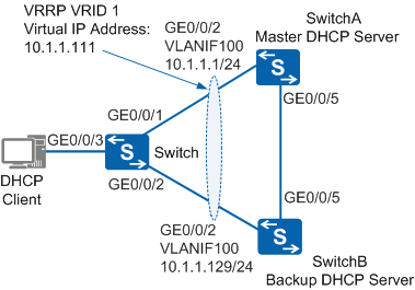
As shown in Figure 1, a host in an enterprise is dual-homed to SwitchA and SwitchB through Switch. SwitchA functions as the master DHCP server to allocate IP addresses to the host. If the master DHCP server fails, a backup DHCP server must allocate an IP address to the host.
Configuration Roadmap
The configuration roadmap is as follows:
- Configure IP addresses for interfaces connecting SwitchA and SwitchB to implement network-layer connectivity. Configure Switch to transparently transmit Layer 2 packets.
- Configure a VRRP group on SwitchA and SwitchB. SwitchA has a higher priority and functions as the DHCP server to allocate IP addresses to clients. SwitchB has a lower priority and functions as a backup DHCP server.
- Create global address pools on SwitchA and SwitchB, and set corresponding attributes.
- Configure a loop prevention protocol on Switch, SwitchA, and SwitchB to prevent loops. In this example, STP is configured.
Procedure
- Configure network-layer connectivity among devices.
# Configure IP addresses for interfaces connecting SwitchA and SwitchB. SwitchA is used as an example. The configuration on SwitchB is similar to that on SwitchA. For details, see the configuration file of SwitchB.
<HUAWEI> system-view
[HUAWEI] sysname SwitchA
[SwitchA] vlan batch 100
[SwitchA] interface gigabitethernet 0/0/2
[SwitchA-GigabitEthernet0/0/2] port link-type hybrid
[SwitchA-GigabitEthernet0/0/2] port hybrid pvid vlan 100
[SwitchA-GigabitEthernet0/0/2] port hybrid untagged vlan 100
[SwitchA-GigabitEthernet0/0/2] quit
[SwitchA] interface gigabitethernet 0/0/5
[SwitchA-GigabitEthernet0/0/5] port link-type hybrid
[SwitchA-GigabitEthernet0/0/5] port hybrid pvid vlan 100
[SwitchA-GigabitEthernet0/0/5] port hybrid untagged vlan 100
[SwitchA-GigabitEthernet0/0/5] quit
[SwitchA] interface vlanif 100
[SwitchA-Vlanif100] ip address 10.1.1.1 24
[SwitchA-Vlanif100] quit
# Configure Layer 2 transparent transmission on Switch.
<HUAWEI> system-view
[HUAWEI] sysname Switch
[Switch] vlan 100
[Switch-vlan100] quit
[Switch] interface gigabitethernet 0/0/1
[Switch-GigabitEthernet0/0/1] port link-type hybrid
[Switch-GigabitEthernet0/0/1] port hybrid pvid vlan 100
[Switch-GigabitEthernet0/0/1] port hybrid untagged vlan 100
[Switch-GigabitEthernet0/0/1] quit
[Switch] interface gigabitethernet 0/0/2
[Switch-GigabitEthernet0/0/2] port link-type hybrid
[Switch-GigabitEthernet0/0/2] port hybrid pvid vlan 100
[Switch-GigabitEthernet0/0/2] port hybrid untagged vlan 100
[Switch-GigabitEthernet0/0/2] quit
[Switch] interface gigabitethernet 0/0/3
[Switch-GigabitEthernet0/0/3] port link-type access
[Switch-GigabitEthernet0/0/3] port default vlan 100
[Switch-GigabitEthernet0/0/3] quit
- Create address pools and set corresponding attributes.
# Enable DHCP on SwitchA.
[SwitchA] dhcp enable
# Create an address pool on SwitchA and specify an IP address range 10.1.1.2 to 10.1.1.128, which is exclusive from the IP address range of the address pool on SwitchB.
Information about the address pool on the master DHCP server cannot be backed up to a backup DHCP server in real time. To prevent IP address conflicts after a master/backup switchover, ensure that the address pool ranges on the master and backup DHCP servers are exclusive to one another.
[SwitchA] ip pool 1
[SwitchA-ip-pool-1] network 10.1.1.0 mask 255.255.255.0
[SwitchA-ip-pool-1] gateway-list 10.1.1.111
[SwitchA-ip-pool-1] excluded-ip-address 10.1.1.1
[SwitchA-ip-pool-1] excluded-ip-address 10.1.1.129 10.1.1.254
[SwitchA-ip-pool-1] lease day 10
[SwitchA-ip-pool-1] quit
# Create an address pool on SwitchB and specify an IP address range 10.1.1.130 to 10.1.1.254, which is exclusive from the IP address range of the address pool on SwitchA.
[SwitchB] dhcp enable
[SwitchB] ip pool 1
[SwitchB-ip-pool-1] network 10.1.1.0 mask 255.255.255.0
[SwitchB-ip-pool-1] gateway-list 10.1.1.111
[SwitchB-ip-pool-1] excluded-ip-address 10.1.1.1 10.1.1.110
[SwitchB-ip-pool-1] excluded-ip-address 10.1.1.112 10.1.1.129
[SwitchB-ip-pool-1] lease day 10
[SwitchB-ip-pool-1] quit
- Configure a VRRP group.
# Create VRRP group 1 on SwitchA, set the priority of SwitchA in the VRRP group to 120, and configure clients to obtain IP addresses from a global address pool.
[SwitchA] interface vlanif 100
[SwitchA-Vlanif100] vrrp vrid 1 virtual-ip 10.1.1.111
[SwitchA-Vlanif100] vrrp vrid 1 priority 120
[SwitchA-Vlanif100] dhcp select global
[SwitchA-Vlanif100] quit
# Create VRRP group 1 on SwitchB, set the priority of SwitchB in the VRRP group to 100 (default), and configure clients to obtain IP addresses from a global address pool.
[SwitchB] interface vlanif 100
[SwitchB-Vlanif100] vrrp vrid 1 virtual-ip 10.1.1.111
[SwitchB-Vlanif100] dhcp select global
[SwitchB-Vlanif100] quit
- Configure STP to prevent loops.
# Enable STP globally on Switch. The configurations on SwitchA and SwitchB are similar to that on Switch. For details, see the configuration files of SwitchA and SwitchB.
[Switch] stp enable
# Disable STP on GE0/0/3 of Switch, and set the path cost of GE0/0/1 to 20000.
[Switch] interface gigabitethernet 0/0/3
[Switch-GigabitEthernet0/0/3] stp disable
[Switch-GigabitEthernet0/0/3] quit
[Switch] interface gigabitethernet 0/0/1
[Switch-GigabitEthernet0/0/1] stp cost 20000
[Switch-GigabitEthernet0/0/1] quit
- Verify the configuration.
# Run the display vrrp command on SwitchA and SwitchB. The command output shows that SwitchA is Master and SwitchB is Backup in the VRRP group.
[SwitchA] display vrrp
  Vlanif100 | Virtual Router 1
    State : Master
    Virtual IP : 10.1.1.111
    Master IP : 10.1.1.1
    PriorityRun : 120
    PriorityConfig : 120
    MasterPriority : 120
    Preempt : YES   Delay Time : 0 s
    TimerRun : 1 s
    TimerConfig : 1 s
    Auth type : NONE
    Virtual MAC : 0000-5e00-0101
    Check TTL : YES
    Config type : normal-vrrp
    Backup-forward : disabled
    Create time : 2017-01-12 20:15:46
    Last change time : 2017-01-12 20:15:46
[SwitchB] display vrrp Vlanif100 | Virtual Router 1 State : Backup Virtual IP : 10.1.1.111 Master IP : 10.1.1.1 PriorityRun : 100 PriorityConfig : 100 MasterPriority : 120 Preempt : YES Delay Time : 0 s TimerRun : 1 s TimerConfig : 1 s Auth type : NONE Virtual MAC : 0000-5e00-0101 Check TTL : YES Config type : normal-vrrp Backup-forward : disabled Create time : 2017-01-12 20:15:46 Last change time : 2017-01-12 20:15:46# Run the display ip pool command on SwitchA and SwitchB. The command output shows that SwitchA, but not SwitchB, successfully allocated an IP address to the client. The following uses the command output in V200R011C10 as an example.
[SwitchA] display ip pool
 -------------------------------------------------------------------------------
  Pool-name        : 1
  Pool-No          : 0
  Lease            : 10 Days 0 Hours 0 Minutes
  Position         : Local
  Status           : Unlocked
  Gateway-0        : 10.1.1.111
  Network          : 10.1.1.0
  Mask             : 255.255.255.0
  VPN instance     : --
  Conflicted address recycle interval: -
  Address Statistic: Total       :253       Used        :1
                     Idle        :125       Expired     :0
                     Conflict    :0         Disable     :127


  IP address Statistic
    Total       :253
    Used        :1          Idle        :125
    Expired     :0          Conflict    :0          Disable   :127
[SwitchB] display ip pool ------------------------------------------------------------------------------- Pool-name : 1 Pool-No : 0 Lease : 10 Days 0 Hours 0 Minutes Position : Local Status : Unlocked Gateway-0 : 10.1.1.111 Network : 10.1.1.0 Mask : 255.255.255.0 VPN instance : -- Conflicted address recycle interval: - Address Statistic: Total :253 Used :0 Idle :125 Expired :0 Conflict :0 Disable :128 IP address Statistic Total :253 Used :0 Idle :125 Expired :0 Conflict :0 Disable :128# Run the shutdown command on GE0/0/2 and GE0/0/5 of SwitchA to simulate a fault.
[SwitchA] interface gigabitethernet 0/0/2
[SwitchA-GigabitEthernet0/0/2] shutdown
[SwitchA-GigabitEthernet0/0/2] quit
[SwitchA] interface gigabitethernet 0/0/5
[SwitchA-GigabitEthernet0/0/5] shutdown
[SwitchA-GigabitEthernet0/0/5] quit
# Run the display vrrp command on SwitchA and SwitchB. The command output shows that SwitchA is Initialize and SwitchB is Master in the VRRP group.
[SwitchA] display vrrp
  Vlanif100 | Virtual Router 1
    State : Initialize
    Virtual IP : 10.1.1.111
    Master IP : 0.0.0.0
    PriorityRun : 120
    PriorityConfig : 120
    MasterPriority : 0
    Preempt : YES   Delay Time : 0 s
    TimerRun : 1 s
    TimerConfig : 1 s
    Auth type : NONE
    Virtual MAC : 0000-5e00-0101
    Check TTL : YES
    Config type : normal-vrrp
    Backup-forward : disabled
    Create time : 2017-01-12 20:15:46
    Last change time : 2017-01-12 20:15:46
[SwitchB] display vrrp Vlanif100 | Virtual Router 1 State : Master Virtual IP : 10.1.1.111 Master IP : 10.1.1.129 PriorityRun : 100 PriorityConfig : 100 MasterPriority : 100 Preempt : YES Delay Time : 0 s TimerRun : 1 s TimerConfig : 1 s Auth type : NONE Virtual MAC : 0000-5e00-0101 Check TTL : YES Config type : normal-vrrp Backup-forward : disabled Create time : 2017-01-12 20:15:46 Last change time : 2017-01-12 20:15:46# Run the display ip pool command on SwitchB to view the address pool configuration.
[SwitchB] display ip pool
  Pool-name        : 1
  Pool-No          : 0
  Lease            : 10 Days 0 Hours 0 Minutes
  Position         : Local
  Status           : Unlocked
  Gateway-0        : 10.1.1.111
  Network          : 10.1.1.0
  Mask             : 255.255.255.0
  VPN instance     : --
  Conflicted address recycle interval: -
  Address Statistic: Total       :253       Used        :1
                     Idle        :124       Expired     :0
                     Conflict    :0         Disabled    :128


  IP address Statistic
    Total       :253
    Used        :1          Idle        :124
    Expired     :0          Conflict    :0          Disabled  :128
Configuration Files
Configuration file of SwitchA
#
sysname SwitchA
#
vlan batch 100
#
dhcp enable
#
ip pool 1
 gateway-list 10.1.1.111
 network 10.1.1.0 mask 255.255.255.0
 excluded-ip-address 10.1.1.1
 excluded-ip-address 10.1.1.129 10.1.1.254
 lease day 10 hour 0 minute 0
#
interface Vlanif100
 ip address 10.1.1.1 255.255.255.0
 vrrp vrid 1 virtual-ip 10.1.1.111
 vrrp vrid 1 priority 120
 dhcp select global
#
interface GigabitEthernet0/0/2
 port link-type hybrid
 port hybrid pvid vlan 100
 port hybrid untagged vlan 100
#
interface GigabitEthernet0/0/5
 port link-type hybrid
 port hybrid pvid vlan 100
 port hybrid untagged vlan 100
#
return
Configuration file of SwitchB
#
sysname SwitchB
#
vlan batch 100
#
dhcp enable
#
ip pool 1
 gateway-list 10.1.1.111
 network 10.1.1.0 mask 255.255.255.0
 excluded-ip-address 10.1.1.1 10.1.1.110
 excluded-ip-address 10.1.1.112 10.1.1.129
 lease day 10 hour 0 minute 0
#
interface Vlanif100
 ip address 10.1.1.129 255.255.255.0
 vrrp vrid 1 virtual-ip 10.1.1.111
 dhcp select global
#
interface GigabitEthernet0/0/2
 port link-type hybrid
 port hybrid pvid vlan 100
 port hybrid untagged vlan 100
#
interface GigabitEthernet0/0/5
 port link-type hybrid
 port hybrid pvid vlan 100
 port hybrid untagged vlan 100
#
return
Configuration file of Switch
#
sysname Switch
#
vlan batch 100
#
interface GigabitEthernet0/0/1
 port link-type hybrid
 port hybrid pvid vlan 100
 port hybrid untagged vlan 100
 stp instance 0 cost 20000
#
interface GigabitEthernet0/0/2
 port link-type hybrid
 port hybrid pvid vlan 100
 port hybrid untagged vlan 100
#
interface GigabitEthernet0/0/3
 port link-type access
 port default vlan 100
 stp disable
#
return
Applicable Product Models and Versions
Series |
Product Model |
Software Version |
|---|---|---|
S2700 |
S2720-EI |
V200R011C10, V200R012C00, V200R013C00, V200R019C00, V200R019C10 |
S3700 |
S3700-EI |
V100R006C05 |
S3700-HI |
V200R001C00 |
|
S5700 |
S5700-EI |
V200R001(C00&C01), V200R002C00, V200R003C00, V200R005(C00&C01&C02&C03) |
S5700-HI |
V200R001(C00&C01), V200R002C00, V200R003C00, V200R005(C00SPC500&C01&C02) |
|
S5710-EI |
V200R001C00, V200R002C00, V200R003C00, V200R005(C00&C02) |
|
S5710-HI |
V200R003C00, V200R005(C00&C02&C03) |
|
S5720-LI, S5720S-LI |
V200R010C00, V200R011C00, V200R011C10, V200R012(C00&C20), V200R013C00, V200R019C00, V200R019C10 |
|
S5720-SI, S5720S-SI |
V200R008C00, V200R009C00, V200R010C00, V200R011C00, V200R011C10, V200R012C00, V200R013C00, V200R019C00, V200R019C10 |
|
S5720I-SI |
V200R012C00, V200R013C00, V200R019C00, V200R019C10 |
|
S5720-EI |
V200R007C00, V200R008C00, V200R009C00, V200R010C00, V200R011C00, V200R011C10, V200R012C00, V200R013C00, V200R019C00, V200R019C10 |
|
S5720-HI |
V200R006C00, V200R007(C00&C10), V200R008C00, V200R009C00, V200R010C00, V200R011C00, V200R011C10, V200R012C00, V200R013C00, V200R019C00, V200R019C10 |
|
S5730-HI |
V200R012C00, V200R013C00, V200R019C00, V200R019C10 |
|
S5730-SI |
V200R011C10, V200R012C00, V200R013C00, V200R019C00, V200R019C10 |
|
S5730S-EI |
V200R011C10, V200R012C00, V200R013C00, V200R019C00, V200R019C10 |
|
S5731-H |
V200R013C02, V200R019C00, V200R019C10 |
|
S5731-S, S5731S-S |
V200R019C00, V200R019C10 |
|
S5731S-H |
V200R019C00, V200R019C10 |
|
S5732-H |
V200R019C00, V200R019C10 |
|
S5735-L, S5735S-L |
V200R019C00, V200R019C10 |
|
S5735S-L-M |
V200R019C00, V200R019C10 |
|
S5735-S, S5735S-S |
V200R019C00, V200R019C10 |
|
S5700 |
S5735-S-I |
V200R019C10 |
S6700 |
S6700-EI |
V200R001(C00&C01), V200R002C00, V200R003C00, V200R005(C00&C01&C02) |
S6720-LI, S6720S-LI |
V200R011C00, V200R011C10, V200R012C00, V200R013C00, V200R019C00, V200R019C10 |
|
S6720-SI, S6720S-SI |
V200R011C00, V200R011C10, V200R012C00, V200R013C00, V200R019C00, V200R019C10 |
|
S6720-EI |
V200R008C00, V200R009C00, V200R010C00, V200R011C00, V200R011C10, V200R012C00, V200R013C00, V200R019C00, V200R019C10 |
|
S6720S-EI |
V200R009C00, V200R010C00, V200R011C00, V200R011C10, V200R012C00, V200R013C00, V200R019C00, V200R019C10 |
|
S6720-HI |
V200R012C00, V200R013C00, V200R019C00, V200R019C10 |
|
S6730-H |
V200R013C02, V200R019C00, V200R019C10 |
|
S6730-S, S6730S-S |
V200R019C00, V200R019C10 |
|
S6730S-H |
V200R019C10 |
|
S7700 |
S7703, S7706, S7712 |
V200R001(C00&C01), V200R002C00, V200R003C00, V200R005C00, V200R006C00, V200R007C00, V200R008C00, V200R009C00, V200R010C00, V200R011C10, V200R012C00, V200R013C00, V200R013C02, V200R019C00, V200R019C10 |
S7703 PoE |
V200R013C00, V200R019C00, V200R019C10 |
|
S7706 PoE |
V200R013C00, V200R019C00, V200R019C10 |
|
S9700 |
S9703, S9706, S9712 |
V200R001(C00&C01), V200R002C00, V200R003C00, V200R005C00, V200R006C00, V200R007(C00&C10), V200R008C00, V200R009C00, V200R010C00, V200R011C10, V200R012C00, V200R013C00 |