Example for Associating the BFD Session Status with the Interface Status
BFD Overview
A network device must detect a communication fault between adjacent devices quickly so that measures can be taken immediately and service interruptions can be prevented. In practice, hardware detection is used to detect link faults. For example, Synchronous Digital Hierarchy (SDH) alarms are used to report link faults. However, not all media can provide the hardware detection mechanism. Applications use the Hello mechanism of the upper-layer routing protocol to detect faults. Detection using this mechanism takes more than 1 second, which is too long for some applications. On a Layer 3 network, the Hello packet detection mechanism cannot detect faults for all routes, such as static routes. This means that a fault between interconnected systems is difficult to locate.
BFD provides fast fault detection independent of media and routing protocols. With the millisecond-level fault detection and switching, BFD is suitable for scenarios that are sensitive to the packet loss and delay.
Configuration Notes
The local discriminator of the local system and the remote discriminator of the remote system must be the same. If the local discriminator of the local system and the remote discriminator of the remote system are different, a static BFD session cannot be set up. After the local discriminator and the remote discriminator are configured, you cannot modify them.
If a BFD session is bound to the default multicast address, the local discriminator and the remote discriminator must be different.
If the WTR time is set, set the same WTR time on both devices. Otherwise, when the BFD session status changes on one device, applications on both devices detect different BFD session statuses.
For applicable product models and versions, see Applicable Product Models and Versions.

For details about software mappings, visit Hardware Query Tool and search for the desired product model.
Networking Requirements
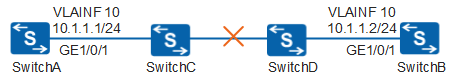
In Figure 1, SwitchA is directly connected to SwitchB at the network layer and Layer 2 transmission devices, SwitchC and SwitchD, are deployed between them. It is required that SwitchA and SwitchB quickly detect link faults of the Layer 2 transmission devices to trigger fast route convergence.
Configuration Roadmap
The configuration roadmap is as follows:
Configure a BFD session on SwitchA and SwitchB to detect faults on the link between SwitchA and SwitchB.
Configure association between the BFD session status and interface status on SwitchA and SwitchB after the BFD session becomes Up.
Procedure
- Set IP addresses of the directly connected interfaces on SwitchA and SwitchB.
# Assign an IP address to the interface of SwitchA.
<HUAWEI> system-view
[HUAWEI] sysname SwitchA
[SwitchA] vlan 10
[SwitchA-vlan10] quit
[SwitchA] interface gigabitethernet 1/0/1
[SwitchA-GigabitEthernet1/0/1] port link-type hybrid   //In V200R005C00 and later versions, the default link type of an interface is not hybrid, you need to configure it manually.
[SwitchA-GigabitEthernet1/0/1] port hybrid pvid vlan 10
[SwitchA-GigabitEthernet1/0/1] port hybrid untagged vlan 10
[SwitchA-GigabitEthernet1/0/1] quit
[SwitchA] interface vlanif 10
[SwitchA-Vlanif10] ip address 10.1.1.1 24
[SwitchA-Vlanif10] quit
# Assign an IP address to the interface of SwitchB.
<HUAWEI> system-view
[HUAWEI] sysname SwitchB
[SwitchB] vlan 10
[SwitchB-vlan10] quit
[SwitchB] interface gigabitethernet 1/0/1
[SwitchA-GigabitEthernet1/0/1] port link-type hybrid   //In V200R005C00 and later versions, the default link type of an interface is not hybrid, you need to configure it manually.
[SwitchB-GigabitEthernet1/0/1] port hybrid pvid vlan 10
[SwitchB-GigabitEthernet1/0/1] port hybrid untagged vlan 10
[SwitchB-GigabitEthernet1/0/1] quit
[SwitchB] interface vlanif 10
[SwitchB-Vlanif10] ip address 10.1.1.2 24
[SwitchB-Vlanif10] quit
- Configure single-hop BFD.
# Enable BFD on SwitchA and establish a BFD session named atob between SwitchA and SwitchB.
[SwitchA] bfd   //Enable BFD globally.
[SwitchA-bfd] quit
[SwitchA] bfd atob bind peer-ip default-ip interface gigabitethernet 1/0/1   //Configure a BFD session named atob.
[SwitchA-bfd-session-atob] discriminator local 10   //Configure the local discriminator of the BFD session. The local discriminator on SwitchA must be the same as the remote discriminator on SwitchB.
[SwitchA-bfd-session-atob] discriminator remote 20   //Configure the remote discriminator of the BFD session. The remote discriminator on SwitchA must be the same as the local discriminator on SwitchB.
[SwitchA-bfd-session-atob] commit   //Commit the BFD session to make the configuration take effect.
[SwitchA-bfd-session-atob] quit
# Enable BFD on SwitchB and establish a BFD session named btoa between SwitchB and SwitchA.
[SwitchB] bfd
[SwitchB-bfd] quit
[SwitchB] bfd btoa bind peer-ip default-ip interface gigabitethernet 1/0/1   //Configure a BFD session named btoa.
[SwitchB-bfd-session-btoa] discriminator local 20
[SwitchB-bfd-session-btoa] discriminator remote 10
[SwitchB-bfd-session-btoa] commit
[SwitchB-bfd-session-btoa] quit
# After the configuration is complete, run the display bfd session all verbose command on SwitchA and SwitchB. You can see that a single-hop BFD session is set up and its status is Up. The display on SwitchA is used as an example.
[SwitchA] display bfd session all verbose
--------------------------------------------------------------------------------
Session MIndex : 16384     (One Hop) State : Up        Name : atob
--------------------------------------------------------------------------------
  Local Discriminator    : 10               Remote Discriminator   : 20
  Session Detect Mode    : Asynchronous Mode Without Echo Function
  BFD Bind Type          : Interface(GigabitEthernet1/0/1)
  Bind Session Type      : Static
  Bind Peer Ip Address   : 224.0.0.184
  NextHop Ip Address     : 224.0.0.184
  Bind Interface         : GigabitEthernet1/0/1
  FSM Board Id           : 3                TOS-EXP                : 7
  Min Tx Interval (ms)   : 1000             Min Rx Interval (ms)   : 1000
  Actual Tx Interval (ms): 1000             Actual Rx Interval (ms): 1000
  Local Detect Multi     : 3                Detect Interval (ms)   : 3000
  Echo Passive           : Disable          Acl Number             : -
  Destination Port       : 3784             TTL                    : 255
  Proc interface status  : Disable          Process PST            : Disable
  WTR Interval (ms)      : -
  Active Multi           : 3
  Last Local Diagnostic  : No Diagnostic
  Bind Application       : No Application Bind
  Session TX TmrID       : -                Session Detect TmrID   : -
  Session Init TmrID     : -                Session WTR TmrID      : -
  Session Echo Tx TmrID  : -
  PDT Index              : FSM-0 | RCV-0 | IF-0 | TOKEN-0
  Session Description    : -
--------------------------------------------------------------------------------

     Total UP/DOWN Session Number : 1/0
- Configuring association between BFD session status and interface status.
# Configure association between the BFD session status and the interface status on SwitchA.
[SwitchA] bfd atob
[SwitchA-bfd-session-atob] process-interface-status
[SwitchA-bfd-session-atob] quit
# Configure association between the BFD session status and the interface status on SwitchB.
[SwitchB] bfd btoa
[SwitchB-bfd-session-btoa] process-interface-status
[SwitchB-bfd-session-btoa] quit
- Verify the configuration.
After the configuration is complete, run the display bfd session all verbose command on SwitchA and SwitchB. You can see that the Proc interface status field is Enable.
The display on SwitchA is used as an example.
[SwitchA] display bfd session all verbose
--------------------------------------------------------------------------------
Session MIndex : 16384     (One Hop) State : Up        Name : atob
--------------------------------------------------------------------------------
  Local Discriminator    : 10               Remote Discriminator   : 20
  Session Detect Mode    : Asynchronous Mode Without Echo Function
  BFD Bind Type          : Interface(GigabitEthernet1/0/1)
  Bind Session Type      : Static
  Bind Peer Ip Address   : 224.0.0.184
  NextHop Ip Address     : 224.0.0.184
  Bind Interface         : GigabitEthernet1/0/1
  FSM Board Id           : 3                TOS-EXP                : 7
  Min Tx Interval (ms)   : 1000             Min Rx Interval (ms)   : 1000
  Actual Tx Interval (ms): 13000            Actual Rx Interval (ms): 13000
  Local Detect Multi     : 3                Detect Interval (ms)   : 30
  Echo Passive           : Disable          Acl Number             : -
  Destination Port       : 3784             TTL                    : 255
  Proc interface status  : Enable           Process PST            : Disable
  WTR Interval (ms)      : -
  Active Multi           : 3
  Last Local Diagnostic  : No Diagnostic
  Bind Application       : IFNET
  Session TX TmrID       : -                Session Detect TmrID   : -
  Session Init TmrID     : -                Session WTR TmrID      : -
  Session Echo Tx TmrID  : -
  PDT Index              : FSM-0 | RCV-0 | IF-0 | TOKEN-0
  Session Description    : -
--------------------------------------------------------------------------------

     Total UP/DOWN Session Number : 1/0
Run the shutdown command on GE1/0/1 of SwitchB to make the BFD session go Down.
[SwitchB] interface gigabitethernet 1/0/1
[SwitchB-GigabitEthernet1/0/1] shutdown
[SwitchB-GigabitEthernet1/0/1] quit
Run the display bfd session all verbose and display interface gigabitethernet 1/0/1 commands on SwitchA. You can see that the BFD session status is Down, and the status of GE1/0/1 is UP (BFD status down).
[SwitchA] display bfd session all verbose
--------------------------------------------------------------------------------
Session MIndex : 16384     (One Hop) State : Down      Name : atob
--------------------------------------------------------------------------------
  Local Discriminator    : 10               Remote Discriminator   : 20
  Session Detect Mode    : Asynchronous Mode Without Echo Function
  BFD Bind Type          : Interface(GigabitEthernet1/0/1)
  Bind Session Type      : Static
  Bind Peer Ip Address   : 224.0.0.184
  NextHop Ip Address     : 224.0.0.184
  Bind Interface         : GigabitEthernet1/0/1
  FSM Board Id           : 3                TOS-EXP                : 7
  Min Tx Interval (ms)   : 1000             Min Rx Interval (ms)   : 10
  Actual Tx Interval (ms): 13000            Actual Rx Interval (ms): 13000
  Local Detect Multi     : 3                Detect Interval (ms)   : 30
  Echo Passive           : Disable          Acl Number             : -
  Destination Port       : 3784             TTL                    : 255
  Proc interface status  : Enable          Process PST            : Disable
  WTR Interval (ms)      : -
  Active Multi           : 3
  Last Local Diagnostic  : Control Detection Time Expired
  Bind Application       : IFNET
  Session TX TmrID       : -                Session Detect TmrID   : -
  Session Init TmrID     : -                Session WTR TmrID      : -
  Session Echo Tx TmrID  : -
  PDT Index              : FSM-0 | RCV-0 | IF-0 | TOKEN-0
  Session Description    : -
--------------------------------------------------------------------------------

     Total UP/DOWN Session Number : 0/1
[SwitchA] display interface gigabitethernet 1/0/1
GigabitEthernet1/0/1 current state : UP
Line protocol current state : UP(BFD status down)
...
Only important information is listed under the display interface gigabitethernet 1/0/1 command, and "..." indicates that information is omitted.
Configuration Files
Configuration file of SwitchA
#
sysname SwitchA
#
vlan batch 10
#
 bfd
#
interface Vlanif10
 ip address 10.1.1.1 255.255.255.0
#
interface GigabitEthernet1/0/1
 port hybrid pvid vlan 10
 port hybrid untagged vlan 10
#
bfd atob bind peer-ip default-ip interface GigabitEthernet1/0/1
 discriminator local 10
 discriminator remote 20
 process-interface-status
 commit
#
return
Configuration file of SwitchB
#
sysname SwitchB
#
vlan batch 10
#
 bfd
#
interface Vlanif10
 ip address 10.1.1.2 255.255.255.0
#
interface GigabitEthernet1/0/1
 port hybrid pvid vlan 10
 port hybrid untagged vlan10
#
bfd btoa bind peer-ip default-ip interface GigabitEthernet1/0/1
 discriminator local 20
 discriminator remote 10
 process-interface-status
 commit
#
return
Applicable Product Models and Versions
Product |
Product Model |
Software Version |
|---|---|---|
S3700 |
S3700-EI |
V100R006C05 |
S3700-HI |
V200R001C00 |
|
S5700 |
S5720-SI, S5720S-SI |
V200R008C00, V200R009C00, V200R010C00, V200R011C00, V200R011C10, V200R012C00, V200R013C00, V200R019C00, V200R019C10 |
S5720I-SI |
V200R012C00, V200R013C00, V200R019C00, V200R019C10 |
|
S5700-EI |
V200R001(C00&C01), V200R002C00, V200R003C00, V200R005(C00&C01&C02&C03) |
|
S5700-HI |
V200R001(C00&C01), V200R002C00, V200R003C00, V200R005(C00SPC500&C01&C02) |
|
S5710-EI |
V200R001C00, V200R002C00, V200R003C00, V200R005(C00&C02) |
|
S5720-EI |
V200R007C00, V200R008C00, V200R009C00, V200R010C00, V200R011C00, V200R011C10, V200R012C00, V200R013C00, V200R019C00, V200R019C10 |
|
S5710-HI |
V200R003C00, V200R005(C00&C02&C03) |
|
S5720-HI |
V200R006C00, V200R007(C00&C10), V200R008C00, V200R009C00, V200R010C00, V200R011C00, V200R011C10, V200R012C00, V200R013C00, V200R019C00, V200R019C10 |
|
S5730-HI |
V200R012C00, V200R013C00, V200R019C00, V200R019C10 |
|
S5730-SI |
V200R011C10, V200R012C00, V200R013C00, V200R019C00, V200R019C10 |
|
S5730S-EI |
V200R011C10, V200R012C00, V200R013C00, V200R019C00, V200R019C10 |
|
S5731-H |
V200R013C02, V200R019C00, V200R019C10 |
|
S5731-S, S5731S-S |
V200R019C00, V200R019C10 |
|
S5731S-H |
V200R019C00, V200R019C10 |
|
S5732-H |
V200R019C00, V200R019C10 |
|
S5735-S-I |
V200R019C10 |
|
S5735-S, S5735S-S |
V200R019C00, V200R019C10 |
|
S6700 |
S6720-SI, S6720S-SI |
V200R011C00, V200R011C10, V200R012C00, V200R013C00, V200R019C00, V200R019C10 |
S6700-EI |
V200R001(C00&C01), V200R002C00, V200R003C00, V200R005(C00&C01&C02) |
|
S6720-EI |
V200R008C00, V200R009C00, V200R010C00, V200R011C00, V200R011C10, V200R012C00, V200R013C00, V200R019C00, V200R019C10 |
|
S6720S-EI |
V200R009C00, V200R010C00, V200R011C00, V200R011C10, V200R012C00, V200R013C00, V200R019C00, V200R019C10 |
|
S6720-HI |
V200R012C00, V200R013C00, V200R019C00, V200R019C10 |
|
S6730-H |
V200R013C02, V200R019C00, V200R019C10 |
|
S6730S-H |
V200R019C10 |
|
S6730-S, S6730S-S |
V200R019C00, V200R019C10 |
|
S7700 |
S7703, S7706, S7712 |
V200R001(C00&C01), V200R002C00, V200R003C00, V200R005C00, V200R006C00, V200R007C00, V200R008C00, V200R009C00, V200R010C00, V200R011C10, V200R012C00, V200R013C00, V200R013C02, V200R019C00, V200R019C10 |
S7703 PoE |
V200R013C00, V200R019C00, V200R019C10 |
|
S7706 PoE |
V200R013C00, V200R019C00, V200R019C10 |
|
S9700 |
S9703, S9706, S9712 |
V200R001(C00&C01), V200R002C00, V200R003C00, V200R005C00, V200R006C00, V200R007(C00&C10), V200R008C00, V200R009C00, V200R010C00, V200R011C10, V200R012C00, V200R013C00 |