Example for Configuring a Combo Interface
Overview
A combo interface consists of a GE electrical interface and a GE optical interface on the panel. The multiplexed electrical and optical interfaces cannot work at the same time. When one interface works, the other interface is disabled. You can use the electrical or optical interface according to networking requirements.
The electrical and optical interfaces share one interface view. When you enable the electrical or optical interface, configure the interface attributes (such as the rate and duplex mode) in the same interface view.
Configuration Notes
- Usage restrictions:
- The electrical and optical interfaces of a combo interface are multiplexed. The optical interface cannot have a copper module installed.
- When a combo interface works in auto mode and the combo optical interface has an optical module installed, the combo interface works as an optical interface after the device restarts.
- You can configure the working mode of the combo interface based on the remote interface type. If the local combo electrical interface is connected to a remote electrical interface, configure the combo interface to work in copper mode. If the local combo optical interface is connected to a remote optical interface, configure the combo interface to work in fiber mode. If the local combo interface is configured to work in a different mode from the remote interface, the two interfaces cannot communicate.
- This example applies to switches that support the combo interface.
Networking Requirements
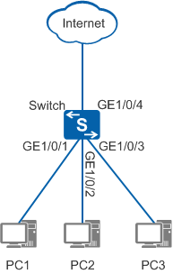
As shown in Figure 1, PC1, PC2, and PC3 connect to GE1/0/1, GE1/0/2 and GE1/0/3 of the Switch respectively. The Switch connects to the Internet through the combo interface GE1/0/4. You can configure the working mode of the combo interface based on the remote interface type. In this example, the remote interface at the Internet side is an electrical interface.
Configuration Roadmap
The configuration roadmap is as follows:
- Configure the combo interface to work as an electrical interface. This configuration ensures that the combo interface's working mode does not change when the transmission medium changes, for example, a GE optical module is installed.
Procedure
- Configure the combo interface GE1/0/4 to work as an electrical interface.
<HUAWEI> system-view
[HUAWEI] sysname Switch
[Switch] interface gigabitethernet 1/0/4
[Switch-GigabitEthernet1/0/4] combo-port copper   //Configure the combo interface to work as an electrical interface. By default, the combo interface's working mode is auto.
[Switch-GigabitEthernet1/0/4] quit
- Verify the configuration.
Run the display interface gigabitethernet 1/0/4 command in any view to check the working mode of the combo interface.
[Switch] display interface gigabitethernet 1/0/4
...
Port Mode: FORCE COPPER
Speed : 1000,   Loopback: NONE
Duplex: FULL,   Negotiation: ENABLE
Mdi   : AUTO,   Flow-control: DISABLE
...
If COMBO AUTO is displayed, the combo interface automatically selects the working mode. If FORCE FIBER is displayed, the combo interface is configured to work as an optical interface. If FORCE COPPER is displayed, the combo interface is configured to work as an electrical interface. The preceding command output shows that the combo interface is configured to work as an electrical interface.