Example for Configuring Port Isolation
Overview
To implement Layer 2 isolation between interfaces, you can add each interface to a different VLAN. However, this method wastes VLAN resources. Port isolation can isolate interfaces in the same VLAN, and a port isolation group can effectively implement Layer 2 isolation between these interfaces. Port isolation provides secure and flexible networking solutions.
- To isolate broadcast packets in the same VLAN but allow users connecting to different interfaces to communicate at Layer 3, you can set the port isolation mode to Layer 2 isolation and Layer 3 interworking.
- To prevent interfaces in the same VLAN from communicating at both Layer 2 and Layer 3, you can set the port isolation mode to Layer 2 and Layer 3 isolation.
Configuration Notes
- This example applies to all versions of all S series switches.
- Do not add both the uplink and downlink interfaces to the same port isolation group unless required. Otherwise, the uplink and downlink interfaces cannot communicate.
- S series switches support Layer 2 isolation and Layer 3 interworking.
- All S series chassis switches support Layer 2 and Layer 3 isolation. S series box switches support Layer 2 and Layer 3 isolation excluding the S2700-SI and S2700-EI running V100R006C05 and the S2720-EI, S5720-LI, S6720-LI, S6720S-LI, S5710-C-LI, and S5720S-LI running V200R001 and later versions.
Networking Requirements
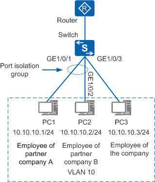
An R&D office of a company contains employees from the company, partner company A, and partner company B. As shown in Figure 1, PC1 and PC2 are used by two employees from partner companies A and B respectively, and PC3 is used by an R&D employee from the company. The requirements are as follows:
- VLAN resources need to be saved.
- Employees from partner companies A and B cannot communicate with each other.
- Employees from partner companies A and B can communicate with the company's employees.
Configuration Roadmap
The configuration roadmap is as follows:
Add interfaces to a VLAN.
Add the interfaces to a port isolation group to implement Layer 2 isolation between these interfaces. The default port isolation mode is Layer 2 isolation and Layer 3 interworking.
Procedure
- Configure port isolation.
# Configure port isolation on GE1/0/1.
<HUAWEI> system-view
[HUAWEI] sysname Switch
[Switch] vlan 10
[Switch-vlan10] quit
[Switch] interface gigabitethernet 1/0/1
[Switch-GigabitEthernet1/0/1] port link-type access   //Set the interface type of GE1/0/1 to access.
[Switch-GigabitEthernet1/0/1] port default vlan 10   //Add GE1/0/1 to VLAN 10.
[Switch-GigabitEthernet1/0/1] port-isolate enable   //By default, the interface is added to port isolation group 1 and the port isolation mode is Layer 2 isolation and Layer 3 interworking. You can run the port-isolate mode all command to set the port isolation mode to Layer 2 and Layer 3 isolation.
[Switch-GigabitEthernet1/0/1] quit
# Configure port isolation on GE1/0/2.
[Switch] interface gigabitethernet 1/0/2
[Switch-GigabitEthernet1/0/2] port link-type access   //Set the interface type of GE1/0/2 to access.
[Switch-GigabitEthernet1/0/2] port default vlan 10   //Add GE1/0/2 to VLAN 10.
[Switch-GigabitEthernet1/0/2] port-isolate enable   //By default, the interface is added to port isolation group 1 and the port isolation mode is Layer 2 isolation and Layer 3 interworking. You can run the port-isolate mode all command to set the port isolation mode to Layer 2 and Layer 3 isolation.
[Switch-GigabitEthernet1/0/2] quit
# Add GE1/0/3 to VLAN 10.
[Switch] interface gigabitethernet 1/0/3
[Switch-GigabitEthernet1/0/3] port link-type access   //Set the interface type of GE1/0/3 to access.
[Switch-GigabitEthernet1/0/3] port default vlan 10   //Add GE1/0/3 to VLAN 10.
[Switch-GigabitEthernet1/0/3] quit
- Verify the configuration.
# PC1 and PC2 cannot communicate with each other.
# PC1 and PC3 can communicate with each other.
# PC2 and PC3 can communicate with each other.
Configuration File
Switch configuration file
#
sysname Switch
#
vlan batch 10
#
interface GigabitEthernet1/0/1
 port link-type access
 port default vlan 10
 port-isolate enable group 1
#
interface GigabitEthernet1/0/2
 port link-type access
 port default vlan 10
 port-isolate enable group 1
#
interface GigabitEthernet1/0/3
 port link-type access
 port default vlan 10
#
return