Example for Configuring Basic OSPF Functions
OSPF Overview
The Open Shortest Path First (OSPF) protocol is a link-state Interior Gateway Protocol (IGP) developed by the Internet Engineering Task Force (IETF). OSPF Version 2 defined in RFC 2328 is used in IPv4.
OSPF is loop-free, provides fast route convergence, and supports area partitioning, equal-cost routes, authentication, and multicast transmission. Therefore, OSPF is widely used as the mainstream IGP in various industries, including the enterprise, carrier, government, finance, education, and health care industries.
OSPF uses the hierarchical design, provides various routing policies, and applies to networks of different sizes and topologies. OSPF is often the first choice for deploying an IGP.
Configuration Notes
- Each router ID in an OSPF process must be unique on an OSPF network. Otherwise, the OSPF neighbor relationship cannot be established and routing information is incorrect. You are advised to configure a unique router ID for each OSPF process on an OSPF device.
- OSPF partitions an AS into different areas, in which Area 0 is the backbone area. OSPF requires that all non-backbone areas maintain the connectivity with the backbone area and devices in the backbone area maintain the connectivity with each other.
- Network types of interfaces on both ends of a link must be the same; otherwise, the two interfaces cannot establish an OSPF neighbor relationship. On a link, if the network type of one OSPF interface is broadcast and the other is P2P, the two OSPF interfaces can still establish an OSPF neighbor relationship but cannot learn routing information from each other.
- The IP address masks of OSPF interfaces on both ends of a link must be the same; otherwise, the two OSPF interfaces cannot establish an OSPF neighbor relationship. On a P2MP network, however, you can run the ospf p2mp-mask-ignore command to disable a device from checking the network mask so that an OSPF neighbor relationship can be established.
- On a broadcast or NBMA network, there must be at least one OSPF interface of which the DR priority is not 0 to ensure that the DR can be elected. Otherwise, the neighbor status of devices on both ends can only be 2-Way.
- For the fixed switch models and versions that support this example, see Applicable Products and Versions.
Networking Requirements
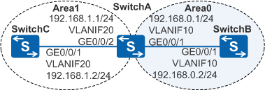
As shown in Figure 1, SwitchA, SwitchB, and SwitchC reside on the OSPF network. The three switches need to communicate with each other, and SwitchA and SwitchB function as core switches to support network expansion.
Configuration Roadmap
The configuration roadmap is as follows:
Configure an IP address for each VLANIF interface on each switch and specify the VLAN to which the interfaces belong to implement interworking.
Configure basic OSPF functions on each switch and partition the OSPF network into Area 0 and Area 1 with SwitchA as the area border router (ABR). Consequently, the area where SwitchA and SwitchB reside becomes the backbone area and can be used to expand the OSPF network.
Procedure
- Specify the VLANs to which interfaces belong.
# Configure SwitchA. The configurations of SwitchB and SwitchC are similar.
<HUAWEI> system-view
[HUAWEI] sysname SwitchA
[SwitchA] vlan batch 10 20
[SwitchA] interface gigabitethernet 0/0/1
[SwitchA-GigabitEthernet0/0/1] port link-type trunk
[SwitchA-GigabitEthernet0/0/1] port trunk allow-pass vlan 10
[SwitchA-GigabitEthernet0/0/1] quit
[SwitchA] interface gigabitethernet 0/0/2
[SwitchA-GigabitEthernet0/0/2] port link-type trunk
[SwitchA-GigabitEthernet0/0/2] port trunk allow-pass vlan 20
[SwitchA-GigabitEthernet0/0/2] quit
- Configure an IP address for each VLANIF interface.
# Configure SwitchA. The configurations of SwitchB and SwitchC are similar.
[SwitchA] interface vlanif 10
[SwitchA-Vlanif10] ip address 192.168.0.1 24
[SwitchA-Vlanif10] quit
[SwitchA] interface vlanif 20
[SwitchA-Vlanif20] ip address 192.168.1.1 24
[SwitchA-Vlanif20] quit
- Configure basic OSPF functions.
# Configure SwitchA.
[SwitchA] ospf 1 router-id 10.1.1.1   //Create an OSPF process 1 with the router ID 10.1.1.1.
[SwitchA-ospf-1] area 0   //Create Area 0 and enter the Area 0 view.
[SwitchA-ospf-1-area-0.0.0.0] network 192.168.0.0 0.0.0.255   //Configure a network segment in Area 0.
[SwitchA-ospf-1-area-0.0.0.0] quit
[SwitchA-ospf-1] area 1   //Create Area 1 and enter the Area 1 view.
[SwitchA-ospf-1-area-0.0.0.1] network 192.168.1.0 0.0.0.255   //Configure a network segment in Area 1.
[SwitchA-ospf-1-area-0.0.0.1] return
# Configure SwitchB.
[SwitchB] ospf 1 router-id 10.2.2.2
[SwitchB-ospf-1] area 0
[SwitchB-ospf-1-area-0.0.0.0] network 192.168.0.0 0.0.0.255
[SwitchB-ospf-1-area-0.0.0.0] return
# Configure SwitchC.
[SwitchC] ospf 1 router-id 10.3.3.3
[SwitchC-ospf-1] area 1
[SwitchC-ospf-1-area-0.0.0.1] network 192.168.1.0 0.0.0.255
[SwitchC-ospf-1-area-0.0.0.1] return
- Verify the configuration.
# Check information about OSPF neighbors of SwitchA.
<SwitchA> display ospf peer

          OSPF Process 1 with Router ID 10.1.1.1
                  Neighbors

 Area 0.0.0.0 interface 192.168.0.1(Vlanif10)'s neighbors
Router ID: 10.2.2.2      Address: 192.168.0.2
   State: Full  Mode:Nbr is  Master  Priority: 1
   DR: 192.168.0.2  BDR: 192.168.0.1   MTU: 0
   Dead timer due in 36  sec
   Retrans timer interval: 5
   Neighbor is up for 00:15:04
   Authentication Sequence: [ 0 ]

                  Neighbors

 Area 0.0.0.1 interface 192.168.1.1(Vlanif20)'s neighbors
Router ID: 10.3.3.3       Address: 192.168.1.2
   State: Full  Mode:Nbr is  Master  Priority: 1
   DR: 192.168.1.2  BDR: 192.168.1.1   MTU: 0
   Dead timer due in 39  sec
   Retrans timer interval: 5
   Neighbor is up for 00:07:32
   Authentication Sequence: [ 0 ]
# Check OSPF routing information on SwitchC.
<SwitchC> display ospf routing

          OSPF Process 1 with Router ID 10.3.3.3
                   Routing Tables

 Routing for Network
 Destination      Cost  Type         NextHop         AdvRouter       Area
 192.168.1.0/24    1    Transit      192.168.1.2     10.3.3.3        0.0.0.1
 192.168.0.0/24    2    Inter-area   192.168.1.1     10.1.1.1        0.0.0.1

 Total Nets: 2
 Intra Area: 1  Inter Area: 1  ASE: 0  NSSA: 0
The preceding command output shows that SwitchC has a route to 192.168.0.0/24 and the route is an inter-area route.
# Check the routing table on SwitchB and perform the ping operation to test the connectivity between SwitchB and SwitchC.
<SwitchB> display ospf routing

          OSPF Process 1 with Router ID 10.2.2.2
                   Routing Tables

 Routing for Network
 Destination        Cost  Type       NextHop      AdvRouter       Area
 192.168.0.0/24     1     Transit    192.168.0.2  10.2.2.2        0.0.0.0
 192.168.1.0/24     2     Inter-area 192.168.0.1  10.1.1.1        0.0.0.0

 Total Nets: 2
 Intra Area: 1  Inter Area: 1  ASE: 0  NSSA: 0
The preceding command output shows that SwitchB has a route to 192.168.1.0/24 and the route is an inter-area route.
# On SwitchB, perform a ping operation to test the connectivity between SwitchB and SwitchC.
<SwitchB> ping 192.168.1.2
  PING 192.168.1.2: 56  data bytes, press CTRL_C to break
    Reply from 192.168.1.2: bytes=56 Sequence=1 ttl=254 time=62 ms
    Reply from 192.168.1.2: bytes=56 Sequence=2 ttl=254 time=16 ms
    Reply from 192.168.1.2: bytes=56 Sequence=3 ttl=254 time=62 ms
    Reply from 192.168.1.2: bytes=56 Sequence=4 ttl=254 time=94 ms
    Reply from 192.168.1.2: bytes=56 Sequence=5 ttl=254 time=63 ms

  --- 192.168.1.2 ping statistics ---
    5 packet(s) transmitted
    5 packet(s) received
    0.00% packet loss
    round-trip min/avg/max = 16/59/94 ms
Configuration Files
SwitchA configuration file
#
sysname SwitchA
#
vlan batch 10 20
#
interface Vlanif10
 ip address 192.168.0.1 255.255.255.0
#
interface Vlanif20
 ip address 192.168.1.1 255.255.255.0
#
interface GigabitEthernet0/0/1
 port link-type trunk
 port trunk allow-pass vlan 10
#
interface GigabitEthernet0/0/2
 port link-type trunk
 port trunk allow-pass vlan 20
#
ospf 1 router-id 10.1.1.1
 area 0.0.0.0
  network 192.168.0.0 0.0.0.255
 area 0.0.0.1
  network 192.168.1.0 0.0.0.255
#
return
SwitchB configuration file
#
sysname SwitchB
#
vlan batch 10
#
interface Vlanif10
 ip address 192.168.0.2 255.255.255.0
#
interface GigabitEthernet0/0/1
 port link-type trunk
 port trunk allow-pass vlan 10
#
ospf 1 router-id 10.2.2.2
 area 0.0.0.0
  network 192.168.0.0 0.0.0.255
#
return
SwitchC configuration file
#
sysname SwitchC
#
vlan batch 20
#
interface Vlanif20
 ip address 192.168.1.2 255.255.255.0
#
interface GigabitEthernet0/0/1
 port link-type trunk
 port trunk allow-pass vlan 20
#
ospf 1 router-id 10.3.3.3
 area 0.0.0.1
  network 192.168.1.0 0.0.0.255
#
return
Applicable Products and Versions
Product |
Product Model |
Software Version |
|---|---|---|
S2700 |
S2720-EI |
V200R011C10, V200R012C00, V200R013C00, V200R019C00, V200R019C10 |
S3700 |
S3700-EI |
V100R006C05 |
S3700-HI |
V200R001C00 |
|
S5700 |
S5700-EI |
V200R001(C00&C01), V200R002C00, V200R003C00, V200R005(C00&C01&C02&C03) |
S5710-EI |
V200R001C00, V200R002C00, V200R003C00, V200R005(C00&C02) |
|
S5720-EI |
V200R007C00, V200R008C00, V200R009C00, V200R010C00, V200R011C00, V200R011C10, V200R012C00, V200R013C00, V200R019C00, V200R019C10 |
|
S5720-SI, S5720S-SI |
V200R008C00, V200R009C00, V200R010C00, V200R011C00, V200R011C10, V200R012C00, V200R013C00, V200R019C00, V200R019C10 |
|
S5720I-SI |
V200R012C00, V200R013C00, V200R019C00, V200R019C10 |
|
S5730-SI |
V200R011C10, V200R012C00, V200R013C00, V200R019C00, V200R019C10 |
|
S5730S-EI |
V200R011C10, V200R012C00, V200R013C00, V200R019C00, V200R019C10 |
|
S5720-LI, S5720S-LI |
V200R010C00, V200R011C00, V200R011C10, V200R012(C00&C20), V200R013C00, V200R019C00, V200R019C10 |
|
S5700-HI |
V200R001(C00&C01), V200R002C00, V200R003C00, V200R005(C00SPC500&C01&C02) |
|
S5710-HI |
V200R003C00, V200R005(C00&C02&C03) |
|
S5720-HI |
V200R006C00, V200R007(C00&C10), V200R008C00, V200R009C00, V200R010C00, V200R011C00, V200R011C10, V200R012C00, V200R013C00, V200R019C00, V200R019C10 |
|
S5730-HI |
V200R012C00, V200R013C00, V200R019C00, V200R019C10 |
|
S5731-H |
V200R013C02, V200R019C00, V200R019C10 |
|
S5731-S, S5731S-S |
V200R019C00, V200R019C10 |
|
S5731S-H |
V200R019C00, V200R019C10 |
|
S5732-H |
V200R019C00, V200R019C10 |
|
S5735-L, S5735S-L |
V200R019C00, V200R019C10 |
|
S5735S-L-M |
V200R019C00, V200R019C10 |
|
S5735-S, S5735S-S |
V200R019C00, V200R019C10 |
|
S5700 |
S5735-S-I |
V200R019C10 |
S6700 |
S6700-EI |
V200R001(C00&C01), V200R002C00, V200R003C00, V200R005(C00&C01&C02) |
S6720-EI |
V200R008C00, V200R009C00, V200R010C00, V200R011C00, V200R011C10, V200R012C00, V200R013C00, V200R019C00, V200R019C10 |
|
S6720S-EI |
V200R009C00, V200R010C00, V200R011C00, V200R011C10, V200R012C00, V200R013C00, V200R019C00, V200R019C10 |
|
S6720-SI, S6720S-SI |
V200R011C00, V200R011C10, V200R012C00, V200R013C00, V200R019C00, V200R019C10 |
|
S6720-LI, S6720S-LI |
V200R011C00, V200R011C10, V200R012C00, V200R013C00, V200R019C00, V200R019C10 |
|
S6720-HI |
V200R012C00, V200R013C00, V200R019C00, V200R019C10 |
|
S6730-H |
V200R013C02, V200R019C00, V200R019C10 |
|
S6730S-H |
V200R019C10 |
|
S6730-S, S6730S-S |
V200R019C00, V200R019C10 |
|
S7700 |
S7703, S7706, S7712 |
V200R001(C00&C01), V200R002C00, V200R003C00, V200R005C00, V200R006C00, V200R007C00, V200R008C00, V200R009C00, V200R010C00, V200R011C10, V200R012C00, V200R013C00, V200R013C02, V200R019C00, V200R019C10 |
S7703 PoE |
V200R013C00, V200R019C00, V200R019C10 |
|
S7706 PoE |
V200R013C00, V200R019C00, V200R019C10 |
|
S9700 |
S9703, S9706, S9712 |
V200R001(C00&C01), V200R002C00, V200R003C00, V200R005C00, V200R006C00, V200R007(C00&C10), V200R008C00, V200R009C00, V200R010C00, V200R011C10, V200R012C00, V200R013C00 |

For details about software mappings, visit Hardware Query Tool and search for the desired product model.