Example for Deploying BGP/MPLS IP VPN and VPLS on One ISP Network
Overview
BGP/MPLS IP VPN is an MPLS-based L3VPN that can be flexibly deployed and easily extended, and is suitable for deployment on a large scale. To add a new site, the network administrator only needs to modify the configuration of the edge nodes serving the new site.
BGP/MPLS IP VPN is suitable for communication between the headquarters and branches in different locations. As communication data needs to traverse the backbone network of the ISP, BGP is used to advertise VPN routes over the backbone network and MPLS is used to forward VPN packets on the backbone network. As different departments of an enterprise need to be isolated, BGP/MPLS IP VPN can isolate route, address space, and access between different VPNs.
VPLS integrates the advantages provided by Ethernet and MPLS. By emulating traditional LAN functions, VPLS enables users who are far apart and on different Ethernet LANs to communicate with each other over the IP/MPLS network provided by the ISP as if they were on the same LAN.
As enterprises set up more and more branches in different regions and office flexibility increases, applications such as instant messaging and teleconferencing are increasingly widely used. This imposes high requirements for end-to-end (E2E) datacom technologies. Multiple enterprise branches distributed in different regions need to communicate over the metropolitan area network (MAN) provided by the ISP. Layer 2 service packets between enterprise branches need to be transmitted over the MAN using the VPLS technology, so that the enterprise branches in different regions can communicate with each other.
The ISP can use the same PE device to provide VPLS and L3VPN services for enterprises to reduce the network construction costs.
Configuration Notes
- The SA series cards cannot be used in this example. The X1E series cards of V200R007 and later versions can be used in this example.
- Applicable products and versions lists applicable products and versions.

For details about software mappings, visit Hardware Query Tool and search for the desired product model.
Networking Requirements
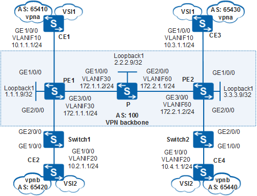
- An ISP provides both VPLS and L3VPN services.
- CE1 connected to the headquarters of enterprise A and CE3 connected to a branch belong to the same VPLS to provide Layer 2 services. CE1 and CE3 are bound to vpna to implement secure transmission of Layer 3 data.
- CE2 connected to the headquarters of enterprise B and CE4 connected to a branch belong to the same VPLS to provide Layer 2 services. CE2 and CE3 are bound to vpna to implement secure transmission of Layer 3 data.
- Selective QinQ needs to be configured on CE-side interfaces on switches to add outer VLAN tags specified by the ISP to the packets sent from CE devices. If a switch connects to multiple CE devices, it can add the same VLAN tag to packets from different CE devices. This saves VLAN IDs on the ISP network.
Data Plan
Device |
Interface |
Sub-interface |
IP Address |
|---|---|---|---|
PE1 |
GigabitEthernet1/0/0 |
GigabitEthernet1/0/0.1 |
10.1.1.2/24 |
PE1 |
GigabitEthernet1/0/0 |
GigabitEthernet1/0/0.2 |
- |
PE1 |
GigabitEthernet2/0/0 |
GigabitEthernet2/0/0.1 |
10.2.1.2/24 |
PE1 |
GigabitEthernet2/0/0 |
GigabitEthernet2/0/0.2 |
- |
PE2 |
GigabitEthernet1/0/0 |
GigabitEthernet1/0/0.1 |
10.3.1.2/24 |
PE2 |
GigabitEthernet1/0/0 |
GigabitEthernet1/0/0.2 |
- |
PE2 |
GigabitEthernet2/0/0 |
GigabitEthernet2/0/0.1 |
10.4.1.2/24 |
PE2 |
GigabitEthernet2/0/0 |
GigabitEthernet2/0/0.2 |
- |
Configuration Roadmap
The configuration roadmap is as follows:
- Configure OSPF between the P and PE devices to ensure IP connectivity on the backbone network.
- Enable basic MPLS capabilities and MPLS LDP on the P and PE devices to set up MPLS LSP tunnels for VPN data transmission on the backbone network.
- Configure MP-IBGP on PE1 and PE2 to enable them to exchange VPN routing information.
- Configure BGP/MPLS IP VPN. Configure L3VPN instances vpna and vpnb on PE1 and PE2. Set the VPN target of vpna to 111:1 and the VPN target of vpnb to 222:2. This configuration allows users in the same VPN to communicate with each other and isolates users of different VPNs. Configure dot1q termination sub-interfaces for single-tagged packets sent from CE1 and CE3. Configure QinQ termination sub-interfaces for double-tagged packets sent from CE2 and CE4.
- Configure the VPLS service. Create VPLS VSI instances on PE1 and PE2. In each VSI instance, specify BGP as the signaling protocol, and set the RD, VPN target and site. Bind sub-interfaces to VSI instances so that the sub-interfaces function as AC interfaces to provide access for VPLS users. Configure dot1q termination sub-interfaces for single-tagged packets sent from CE1 and CE3. Configure QinQ termination sub-interfaces for double-tagged packets sent from CE2 and CE4.
- Configure selective QinQ on CE-side interfaces of the switches and specify the VLANs allowed by the interfaces.
- Set up EBGP peer relationships between the CE and PE devices so that they can exchange VPN routing information.
Procedure
- Configure an IGP protocol on the MPLS backbone network so that the PE and P devices can communicate with each other.
# Configure PE1.
<HUAWEI> system-view
[HUAWEI] sysname PE1
[PE1] interface loopback 1
[PE1-LoopBack1] ip address 1.1.1.9 32
[PE1-LoopBack1] quit
[PE1] vlan batch 30
[PE1] interface gigabitethernet 3/0/0
[PE1-GigabitEthernet3/0/0] port link-type hybrid
[PE1-GigabitEthernet3/0/0] port hybrid pvid vlan 30
[PE1-GigabitEthernet3/0/0] port hybrid untagged vlan 30
[PE1-GigabitEthernet3/0/0] quit
[PE1] interface vlanif 30
[PE1-Vlanif30] ip address 172.1.1.1 24
[PE1-Vlanif30] quit
[PE1] ospf 1 router-id 1.1.1.9
[PE1-ospf-1] area 0
[PE1-ospf-1-area-0.0.0.0] network 172.1.1.0 0.0.0.255
[PE1-ospf-1-area-0.0.0.0] network 1.1.1.9 0.0.0.0
[PE1-ospf-1-area-0.0.0.0] quit
[PE1-ospf-1] quit
# Configure the P.
<HUAWEI> system-view
[HUAWEI] sysname P
[P] interface loopback 1
[P-LoopBack1] ip address 2.2.2.9 32
[P-LoopBack1] quit
[P] vlan batch 30 60
[P] interface gigabitethernet 1/0/0
[P-GigabitEthernet1/0/0] port link-type hybrid
[P-GigabitEthernet1/0/0] port hybrid pvid vlan 30
[P-GigabitEthernet1/0/0] port hybrid untagged vlan 30
[P-GigabitEthernet1/0/0] quit
[P] interface gigabitethernet 2/0/0
[P-GigabitEthernet2/0/0] port link-type hybrid
[P-GigabitEthernet2/0/0] port hybrid pvid vlan 60
[P-GigabitEthernet2/0/0] port hybrid untagged vlan 60
[P-GigabitEthernet2/0/0] quit
[P] interface vlanif 30
[P-Vlanif30] ip address 172.1.1.2 24
[P-Vlanif30] quit
[P] interface vlanif 60
[P-Vlanif60] ip address 172.2.1.1 24
[P-Vlanif60] quit
[P] ospf 1 router-id 2.2.2.9
[P-ospf-1] area 0
[P-ospf-1-area-0.0.0.0] network 172.1.1.0 0.0.0.255
[P-ospf-1-area-0.0.0.0] network 172.2.1.0 0.0.0.255
[P-ospf-1-area-0.0.0.0] network 2.2.2.9 0.0.0.0
[P-ospf-1-area-0.0.0.0] quit
[P-ospf-1] quit
# Configure PE2.
<HUAWEI> system-view
[HUAWEI] sysname PE2
[PE2] interface loopback 1
[PE2-LoopBack1] ip address 3.3.3.9 32
[PE2-LoopBack1] quit
[PE2] vlan batch 60
[PE2] interface gigabitethernet 3/0/0
[PE2-GigabitEthernet3/0/0] port link-type hybrid
[PE2-GigabitEthernet3/0/0] port hybrid pvid vlan 60
[PE2-GigabitEthernet3/0/0] port hybrid untagged vlan 60
[PE2-GigabitEthernet3/0/0] quit
[PE2] interface vlanif 60
[PE2-Vlanif60] ip address 172.2.1.2 24
[PE2-Vlanif60] quit
[PE2] ospf 1 router-id 3.3.3.9
[PE2-ospf-1] area 0
[PE2-ospf-1-area-0.0.0.0] network 172.2.1.0 0.0.0.255
[PE2-ospf-1-area-0.0.0.0] network 3.3.3.9 0.0.0.0
[PE2-ospf-1-area-0.0.0.0] quit
[PE2-ospf-1] quit
After the configuration is complete, OSPF neighbor relationships can be set up between PE1, P, and PE2. Run the display ospf peer command on PE1, P, and PE2, and you can view that the neighbor status is Full. Run the display ip routing-table command on PE1 and PE2, and you can view that PE1 and PE2 have learned the routes to each other's Loopback1 address.
The display on PE1 is used as an example:
[PE1] display ip routing-table
Route Flags: R - relay, D - download to fib, T - to vpn-instance
------------------------------------------------------------------------------
Routing Tables: Public
         Destinations : 8       Routes : 8

  Destination/Mask    Proto  Pre  Cost     Flags NextHop         Interface

         1.1.1.9/32   Direct 0    0           D  127.0.0.1       LoopBack1
         2.2.2.9/32   OSPF   10   1           D  172.1.1.2       Vlanif30
         3.3.3.9/32   OSPF   10   2           D  172.1.1.2       Vlanif30
        127.0.0.0/8   Direct 0    0           D  127.0.0.1       InLoopBack0
       127.0.0.1/32   Direct 0    0           D  127.0.0.1       InLoopBack0
       172.1.1.0/24   Direct 0    0           D  172.1.1.1       Vlanif30
       172.1.1.1/32   Direct 0    0           D  127.0.0.1       Vlanif30
       172.2.1.0/24   OSPF   10   2           D  172.1.1.2       Vlanif30
[PE1] display ospf peer OSPF Process 1 with Router ID 1.1.1.9 Neighbors Area 0.0.0.0 interface 172.1.1.1(Vlanif30)'s neighbors Router ID: 2.2.2.9 Address: 172.1.1.2 State: Full Mode:Nbr is Master Priority: 1 DR: 172.1.1.2 BDR: 172.1.1.1 MTU: 0 Dead timer due in 37 sec Retrans timer interval: 5 Neighbor is up for 00:16:21 Authentication Sequence: [ 0 ] - Enable basic MPLS capabilities and MPLS LDP on the PE devices to set up LDP LSPs on the MPLS backbone network.
# Configure PE1.
[PE1] mpls lsr-id 1.1.1.9
[PE1] mpls
[PE1-mpls] quit
[PE1] mpls ldp
[PE1-mpls-ldp] quit
[PE1] interface vlanif 30
[PE1-Vlanif30] mpls
[PE1-Vlanif30] mpls ldp
[PE1-Vlanif30] quit
# Configure the P.
[P] mpls lsr-id 2.2.2.9
[P] mpls
[P-mpls] quit
[P] mpls ldp
[P-mpls-ldp] quit
[P] interface vlanif 30
[P-Vlanif30] mpls
[P-Vlanif30] mpls ldp
[P-Vlanif30] quit
[P] interface vlanif 60
[P-Vlanif60] mpls
[P-Vlanif60] mpls ldp
[P-Vlanif60] quit
# Configure PE2.
[PE2] mpls lsr-id 3.3.3.9
[PE2] mpls
[PE2-mpls] quit
[PE2] mpls ldp
[PE2-mpls-ldp] quit
[PE2] interface vlanif 60
[PE2-Vlanif60] mpls
[PE2-Vlanif60] mpls ldp
[PE2-Vlanif60] quit
After the configuration is complete, LDP sessions are established between PE1 and the P and between the P and PE2. Run the display mpls ldp session command on PE1, P, and PE2, and you can view that the LDP session status is Operational. Run the display mpls ldp lsp command, and you can view information about the established LDP LSPs.
The display on PE1 is used as an example:
[PE1] display mpls ldp session

 LDP Session(s) in Public Network
 Codes: LAM(Label Advertisement Mode), SsnAge Unit(DDDD:HH:MM)
 A '*' before a session means the session is being deleted.
 ------------------------------------------------------------------------------
 PeerID            Status      LAM  SsnRole  SsnAge       KASent/Rcv
 ------------------------------------------------------------------------------
 2.2.2.9:0          Operational DU   Passive   0000:00:01  6/6
 ------------------------------------------------------------------------------
 TOTAL: 1 session(s) Found.
[PE1] display mpls ldp lsp LDP LSP Information ------------------------------------------------------------------------------- Flag after Out IF: (I) - LSP Is Only Iterated by RLFA ------------------------------------------------------------------------------- DestAddress/Mask In/OutLabel UpstreamPeer NextHop OutInterface ------------------------------------------------------------------------------- 1.1.1.9/32 3/NULL 2.2.2.9 127.0.0.1 InLoop0 *1.1.1.9/32 Liberal/1025 DS/2.2.2.9 2.2.2.9/32 NULL/3 - 172.1.1.2 Vlanif30 2.2.2.9/32 1024/3 2.2.2.9 172.1.1.2 Vlanif30 3.3.3.9/32 NULL/1025 - 172.1.1.2 Vlanif30 3.3.3.9/32 1025/1025 2.2.2.9 172.1.1.2 Vlanif30 ------------------------------------------------------------------------------- TOTAL: 5 Normal LSP(s) Found. TOTAL: 1 Liberal LSP(s) Found. TOTAL: 0 Frr LSP(s) Found. A '*' before an LSP means the LSP is not established A '*' before a Label means the USCB or DSCB is stale A '*' before a UpstreamPeer means the session is stale A '*' before a DS means the session is stale A '*' before a NextHop means the LSP is FRR LSP
- Configure L3VPN instances on the PE devices. Configure dot1q termination sub-interfaces for single-tagged packets from vpna. Configure QinQ termination sub-interfaces for double-tagged packets from vpnb. (Layer 3 service users are identified by VLAN 10 and VLAN 20, and the PE devices use VLAN 10 and VLAN 100 to identify Layer 3 services.)
# Configure PE1.
[PE1] ip vpn-instance vpna
[PE1-vpn-instance-vpna] route-distinguisher 100:1
[PE1-vpn-instance-vpna-af-ipv4] vpn-target 111:1 both
[PE1-vpn-instance-vpna-af-ipv4] quit
[PE1-vpn-instance-vpna] quit
[PE1] ip vpn-instance vpnb
[PE1-vpn-instance-vpnb] route-distinguisher 100:2
[PE1-vpn-instance-vpnb-af-ipv4] vpn-target 222:2 both
[PE1-vpn-instance-vpnb-af-ipv4] quit
[PE1-vpn-instance-vpnb] quit
[PE1] vcmp role silent
[PE1] interface gigabitethernet 1/0/0
[PE1-GigabitEthernet1/0/0] port link-type hybrid
[PE1-GigabitEthernet1/0/0] quit
[PE1] interface gigabitethernet 1/0/0.1
[PE1-GigabitEthernet1/0/0.1] dot1q termination vid 10
[PE1-GigabitEthernet1/0/0.1] ip binding vpn-instance vpna
[PE1-GigabitEthernet1/0/0.1] ip address 10.1.1.2 24
[PE1-GigabitEthernet1/0/0.1] arp broadcast enable
[PE1-GigabitEthernet1/0/0.1] quit
[PE1] interface gigabitethernet 2/0/0
[PE1-GigabitEthernet2/0/0] port link-type hybrid
[PE1-GigabitEthernet2/0/0] quit
[PE1] interface gigabitethernet 2/0/0.1
[PE1-GigabitEthernet2/0/0.1] qinq termination pe-vid 100 ce-vid 20
[PE1-GigabitEthernet2/0/0.1] ip binding vpn-instance vpnb
[PE1-GigabitEthernet2/0/0.1] ip address 10.2.1.2 24
[PE1-GigabitEthernet2/0/0.1] arp broadcast enable
[PE1-GigabitEthernet2/0/0.1] quit
# Configure PE2.
[PE2] ip vpn-instance vpna
[PE2-vpn-instance-vpna] route-distinguisher 200:1
[PE2-vpn-instance-vpna-af-ipv4] vpn-target 111:1 both
[PE2-vpn-instance-vpna-af-ipv4] quit
[PE2-vpn-instance-vpna] quit
[PE2] ip vpn-instance vpnb
[PE2-vpn-instance-vpnb] route-distinguisher 200:2
[PE2-vpn-instance-vpnb-af-ipv4] vpn-target 222:2 both
[PE2-vpn-instance-vpnb-af-ipv4] quit
[PE2-vpn-instance-vpnb] quit
[PE2] vcmp role silent
[PE2] interface gigabitethernet 1/0/0
[PE2-GigabitEthernet1/0/0] port link-type hybrid
[PE2-GigabitEthernet1/0/0] quit
[PE2] interface gigabitethernet 1/0/0.1
[PE2-GigabitEthernet1/0/0.1] dot1q termination vid 10
[PE2-GigabitEthernet1/0/0.1] ip binding vpn-instance vpna
[PE2-GigabitEthernet1/0/0.1] ip address 10.3.1.2 24
[PE2-GigabitEthernet1/0/0.1] arp broadcast enable
[PE2-GigabitEthernet1/0/0.1] quit
[PE2] interface gigabitethernet 2/0/0
[PE2-GigabitEthernet2/0/0] port link-type hybrid
[PE2-GigabitEthernet2/0/0] quit
[PE2] interface gigabitethernet 2/0/0.1
[PE2-GigabitEthernet2/0/0.1] qinq termination pe-vid 100 ce-vid 20
[PE2-GigabitEthernet2/0/0.1] ip binding vpn-instance vpnb
[PE2-GigabitEthernet2/0/0.1] ip address 10.4.1.2 24
[PE2-GigabitEthernet2/0/0.1] arp broadcast enable
[PE2-GigabitEthernet2/0/0.1] quit
# Configure CE1 connecting to the headquarters of enterprise A. Configure IP addresses for interfaces of CE2, CE3, and CE4 according to Figure 1. The configurations of CE2, CE3, and CE4 are similar to the configuration of CE1, and are not mentioned here.
<HUAWEI> system-view
[HUAWEI] sysname CE1
[CE1] vlan batch 10 to 11
[CE1] interface gigabitethernet 1/0/0
[CE1-GigabitEthernet1/0/0] port link-type hybrid
[CE1-GigabitEthernet1/0/0] port hybrid tagged vlan 10 to 11
[CE1-GigabitEthernet1/0/0] quit
[CE1] interface vlanif 10
[CE1-Vlanif10] ip address 10.1.1.1 24
[CE1-Vlanif10] quit
After the configuration is complete, run the display ip vpn-instance verbose command on PE1 and PE2 to view VPN instance configuration. The PE devices can ping CE devices attached to them.
If a PE device has multiple interfaces bound to the same VPN instance, you need to specify a source IP address when pinging the CE device connected to the remote PE device. To specify the source IP address, set the -a source-ip-address parameter in the ping -vpn-instance vpn-instance-name -a source-ip-address dest-ip-address command. If no source IP address is specified, the ping operation fails.
The ping test from PE1 to CE1 is used as an example:
[PE1] display ip vpn-instance verbose
 Total VPN-Instances configured : 2
 Total IPv4 VPN-Instances configured : 2
 Total IPv6 VPN-Instances configured : 0

 VPN-Instance Name and ID : vpna, 1
  Interfaces : GigabitEthernet1/0/0.1
 Address family ipv4
  Create date : 2012/07/25 00:58:17 UTC+08:00
  Up time : 0 days, 22 hours, 24 minutes and 53 seconds
  Route Distinguisher : 100:1
  Export VPN Targets :  111:1
  Import VPN Targets :  111:1
  Label Policy : label per instance
  Per-Instance Label : 4096
  Log Interval : 5

 VPN-Instance Name and ID : vpnb, 2
  Interfaces : GigabitEthernet2/0/0.1
 Address family ipv4
  Create date : 2012/07/25 00:58:17 UTC+08:00
  Up time : 0 days, 22 hours, 24 minutes and 53 seconds
  Route Distinguisher : 100:2
  Export VPN Targets :  222:2
  Import VPN Targets :  222:2
  Label Policy : label per instance
  Per-Instance Label : 4096
  Log Interval : 5
[PE1] ping -vpn-instance vpnb 10.2.1.1 PING 10.1.1.1: 56 data bytes, press CTRL_C to break Reply from 10.1.1.1: bytes=56 Sequence=1 ttl=254 time=5 ms Reply from 10.1.1.1: bytes=56 Sequence=2 ttl=254 time=3 ms Reply from 10.1.1.1: bytes=56 Sequence=3 ttl=254 time=3 ms Reply from 10.1.1.1: bytes=56 Sequence=4 ttl=254 time=3 ms Reply from 10.1.1.1: bytes=56 Sequence=5 ttl=254 time=16 ms --- 10.1.1.1 ping statistics --- 5 packet(s) transmitted 5 packet(s) received 0.00% packet loss round-trip min/avg/max = 3/6/16 ms - Create VPLS VSI instances on PE1 and PE2. In each VSI instance, specify BGP as the signaling protocol, and set the RD, VPN target and site. Bind sub-interfaces to VSI instances so that the sub-interfaces function as AC interfaces to provide access for VPLS users. Configure dot1q termination sub-interfaces for single-tagged packets sent from CE1 and CE3. Configure QinQ termination sub-interfaces for double-tagged packets sent from CE2 and CE4. (The CE devices use VLAN 11 and VLAN 21 to identify Layer 2 service users, and the PE devices use VLAN 11 and VLAN 200 to identify Layer 2 services.)
# Configure PE1.
[PE1] mpls l2vpn
[PE1-l2vpn] quit
[PE1] vsi vsi1 auto
[PE1-vsi-vsi1] pwsignal bgp
[PE1-vsi-vsi1-bgp] route-distinguisher 101:1
[PE1-vsi-vsi1-bgp] vpn-target 100:1 import-extcommunity
[PE1-vsi-vsi1-bgp] vpn-target 100:1 export-extcommunity
[PE1-vsi-vsi1-bgp] site 1 range 5 default-offset 0
[PE1-vsi-vsi1-bgp] quit
[PE1-vsi-vsi1] quit
[PE1] vsi vsi2 auto
[PE1-vsi-vsi2] pwsignal bgp
[PE1-vsi-vsi2-bgp] route-distinguisher 101:2
[PE1-vsi-vsi2-bgp] vpn-target 200:1 import-extcommunity
[PE1-vsi-vsi2-bgp] vpn-target 200:1 export-extcommunity
[PE1-vsi-vsi2-bgp] site 1 range 5 default-offset 0
[PE1-vsi-vsi2-bgp] quit
[PE1-vsi-vsi2] quit
[PE1] interface gigabitethernet 1/0/0.2
[PE1-GigabitEthernet1/0/0.2] dot1q termination vid 11
[PE1-GigabitEthernet1/0/0.2] l2 binding vsi vsi1
[PE1-GigabitEthernet1/0/0.2] quit
[PE1] interface gigabitethernet 2/0/0.2
[PE1-GigabitEthernet2/0/0.2] qinq termination pe-vid 200 ce-vid 21
[PE1-GigabitEthernet2/0/0.2] l2 binding vsi vsi2
[PE1-GigabitEthernet2/0/0.2] quit
# Configure PE2.
[PE2] mpls l2vpn
[PE2-l2vpn] quit
[PE2] vsi vsi1 auto
[PE2-vsi-vsi1] pwsignal bgp
[PE2-vsi-vsi1-bgp] route-distinguisher 201:1
[PE2-vsi-vsi1-bgp] vpn-target 100:1 import-extcommunity
[PE2-vsi-vsi1-bgp] vpn-target 100:1 export-extcommunity
[PE2-vsi-vsi1-bgp] site 2 range 5 default-offset 0
[PE2-vsi-vsi1-bgp] quit
[PE2-vsi-vsi1] quit
[PE2] vsi vsi2 auto
[PE2-vsi-vsi2] pwsignal bgp
[PE2-vsi-vsi2-bgp] route-distinguisher 201:2
[PE2-vsi-vsi2-bgp] vpn-target 200:1 import-extcommunity
[PE2-vsi-vsi2-bgp] vpn-target 200:1 export-extcommunity
[PE2-vsi-vsi2-bgp] site 2 range 5 default-offset 0
[PE2-vsi-vsi2-bgp] quit
[PE2-vsi-vsi2] quit
[PE2] interface gigabitethernet 1/0/0.2
[PE2-GigabitEthernet1/0/0.2] dot1q termination vid 11
[PE2-GigabitEthernet1/0/0.2] l2 binding vsi vsi1
[PE2-GigabitEthernet1/0/0.2] quit
[PE2] interface gigabitethernet 2/0/0.2
[PE2-GigabitEthernet2/0/0.2] qinq termination pe-vid 200 ce-vid 21
[PE2-GigabitEthernet2/0/0.2] l2 binding vsi vsi2
[PE2-GigabitEthernet2/0/0.2] quit
- Set up EBGP peer relationships between the PE and CE devices and import L3VPN routes to BGP.
# Configure CE1 connecting to the headquarters of enterprise A. The configurations of CE2, CE3, and CE4 are similar to that of CE1, and are not mentioned here.
[CE1] bgp 65410
[CE1-bgp] peer 10.1.1.2 as-number 100
[CE1-bgp] import-route direct
[CE1-bgp] quit
# Configure PE1. The configuration of PE2 is similar to that of PE1, and is not mentioned here.
[PE1] bgp 100
[PE1-bgp] ipv4-family vpn-instance vpna
[PE1-bgp-vpna] peer 10.1.1.1 as-number 65410
[PE1-bgp-vpna] import-route direct
[PE1-bgp-vpna] quit
[PE1-bgp] ipv4-family vpn-instance vpnb
[PE1-bgp-vpnb] peer 10.2.1.1 as-number 65420
[PE1-bgp-vpnb] import-route direct
[PE1-bgp-vpnb] quit
[PE1-bgp]quit
After the configuration is complete, run the display bgp vpnv4 vpn-instance vpn-instance-name peer command on the PE devices. You can view that BGP peer relationships between PE and CE devices have been established and are in the Established state.
The BGP peer relationship between PE1 and CE1 is used as an example:
[PE1] display bgp vpnv4 vpn-instance vpna peer BGP local router ID : 1.1.1.9 Local AS number : 100 VPN-Instance vpna, Router ID 1.1.1.9: Total number of peers : 1 Peers in established state : 1 Peer V AS MsgRcvd MsgSent OutQ Up/Down State PrefRcv 10.1.1.1 4 65410 11 9 0 00:07:25 Established 1 - Set up an MP-IBGP peer relationship between PE1 and PE2.
# Configure PE1.
[PE1] bgp 100
[PE1-bgp] peer 3.3.3.9 as-number 100
[PE1-bgp] peer 3.3.3.9 connect-interface loopback 1
[PE1-bgp] ipv4-family vpnv4
[PE1-bgp-af-vpnv4] peer 3.3.3.9 enable
[PE1-bgp-af-vpnv4] quit
[PE1-bgp] vpls-family
[PE1-bgp-af-vpls] peer 3.3.3.9 enable
[PE1-bgp-af-vpls] quit
[PE1-bgp] quit
# Configure PE2.
[PE2] bgp 100
[PE2-bgp] peer 1.1.1.9 as-number 100
[PE2-bgp] peer 1.1.1.9 connect-interface loopback 1
[PE2-bgp] ipv4-family vpnv4
[PE2-bgp-af-vpnv4] peer 1.1.1.9 enable
[PE2-bgp-af-vpnv4] quit
[PE2-bgp] vpls-family
[PE2-bgp-af-vpls] peer 1.1.1.9 enable
[PE2-bgp-af-vpls] quit
[PE2-bgp] quit
- Configure selective QinQ on CE-side interfaces of the switches and specify the VLANs allowed by the interfaces.
# Configure Switch1.
<HUAWEI> system-view
[HUAWEI] sysname Switch1
[Switch1] vlan batch 100 200
[Switch1] interface gigabitethernet 2/0/0
[Switch1-GigabitEthernet2/0/0] port link-type hybrid
[Switch1-GigabitEthernet2/0/0] port hybrid tagged vlan 100 200
[Switch1-GigabitEthernet2/0/0] quit
[Switch1] interface gigabitethernet 1/0/0
[Switch1-GigabitEthernet1/0/0] port link-type hybrid
[Switch1-GigabitEthernet1/0/0] port hybrid untagged vlan 100 200
[Switch1-GigabitEthernet1/0/0] port vlan-stacking vlan 20 stack-vlan 100
[Switch1-GigabitEthernet1/0/0] port vlan-stacking vlan 21 stack-vlan 200
[Switch1-GigabitEthernet1/0/0] quit
# Configure Switch2.
<HUAWEI> system-view
[HUAWEI] sysname Switch2
[Switch2] vlan batch 100 200
[Switch2] interface gigabitethernet 2/0/0
[Switch2-GigabitEthernet2/0/0] port link-type hybrid
[Switch2-GigabitEthernet2/0/0] port hybrid tagged vlan 100 200
[Switch2-GigabitEthernet2/0/0] quit
[Switch2] interface gigabitethernet 1/0/0
[Switch2-GigabitEthernet1/0/0] port link-type hybrid
[Switch2-GigabitEthernet1/0/0] port hybrid untagged vlan 100 200
[Switch2-GigabitEthernet1/0/0] port vlan-stacking vlan 20 stack-vlan 100
[Switch2-GigabitEthernet1/0/0] port vlan-stacking vlan 21 stack-vlan 200
[Switch2-GigabitEthernet1/0/0] quit
- Verify the configuration.
Run the display ip routing-table vpn-instance command on PE1 and PE2 to view the L3VPN routes to the remote CE devices.
The display on PE1 is used as an example:
[PE1] display ip routing-table vpn-instance vpna
Route Flags: R - relay, D - download to fib, T - to vpn-instance
------------------------------------------------------------------------------
Routing Tables: vpna
         Destinations : 3        Routes : 3

Destination/Mask    Proto  Pre  Cost     Flags NextHop         Interface
     10.1.1.0/24    Direct 0    0        D     10.1.1.2        GigabitEthernet1/0/0.1
     10.1.1.2/32    Direct 0    0        D     127.0.0.1       GigabitEthernet1/0/0.1
     10.3.1.0/24    IBGP   255  0        RD    3.3.3.9         GigabitEthernet1/0/0.1
[PE1] display ip routing-table vpn-instance vpnb Route Flags: R - relay, D - download to fib, T - to vpn-instance ------------------------------------------------------------------------------ Routing Tables: vpnb Destinations : 3 Routes : 3 Destination/Mask Proto Pre Cost Flags NextHop Interface 10.2.1.0/24 Direct 0 0 D 10.2.1.2 GigabitEthernet2/0/0.1 10.2.1.2/32 Direct 0 0 D 127.0.0.1 GigabitEthernet2/0/0.1 10.4.1.0/24 IBGP 255 0 RD 3.3.3.9 GigabitEthernet2/0/0.1CE devices in the same VPN instance can successfully ping each other, whereas CE devices in different VPN instances cannot.
For example, CE1 connecting to the headquarters of enterprise A can successfully ping CE3 connecting to a branch at 10.3.1.1 but cannot ping CE4 connecting to the headquarters of enterprise B at 10.4.1.1.
[CE1] ping 10.3.1.1
  PING 10.3.1.1: 56  data bytes, press CTRL_C to break
    Reply from 10.3.1.1: bytes=56 Sequence=1 ttl=253 time=72 ms
    Reply from 10.3.1.1: bytes=56 Sequence=2 ttl=253 time=34 ms
    Reply from 10.3.1.1: bytes=56 Sequence=3 ttl=253 time=50 ms
    Reply from 10.3.1.1: bytes=56 Sequence=4 ttl=253 time=50 ms
    Reply from 10.3.1.1: bytes=56 Sequence=5 ttl=253 time=34 ms
  --- 10.3.1.1 ping statistics ---
    5 packet(s) transmitted
    5 packet(s) received
    0.00% packet loss
    round-trip min/avg/max = 34/48/72 ms
[CE1] ping 10.4.1.1 PING 10.4.1.1: 56 data bytes, press CTRL_C to break Request time out Request time out Request time out Request time out Request time out --- 10.4.1.1 ping statistics --- 5 packet(s) transmitted 0 packet(s) received 100.00% packet lossRun the display vsi name vsi2 verbose command on PE1, and you can view that vsi2 has a PW to PE2 and is in Up state.
[PE1] display vsi name vsi2 verbose

 ***VSI Name               : vsi2
    Administrator VSI      : no
    Isolate Spoken         : disable
    VSI Index              : 1
    PW Signaling           : bgp
    Member Discovery Style : auto
    PW MAC Learn Style     : unqualify
    Encapsulation Type     : vlan
    MTU                    : 1500
    Diffserv Mode          : uniform
    Mpls Exp               : --
    DomainId               : 255
    Domain Name            :
    Ignore AcState         : disable
    P2P VSI                : disable
    Create Time            : 0 days, 0 hours, 22 minutes, 6 seconds
    VSI State              : up

    BGP RD                 : 101:2
    SiteID/Range/Offset    : 1/5/0
    Import vpn target      : 200:1
    Export vpn target      : 200:1
    Remote Label Block     : 35845/5/0
    Local Label Block      : 0/35845/5/0

    Interface Name         : GigabitEthernet2/0/0.2
    State                  : up
    Access Port            : false
    Last Up Time           : 2012/12/24 21:19:48
    Total Up Time          : 0 days, 0 hours, 20 minutes, 42 seconds

  **PW Information:

   *Peer Ip Address        : 3.3.3.9
    PW State               : up
    Local VC Label         : 35847
    Remote VC Label        : 35846
    PW Type                : label
    Local  VCCV            : alert lsp-ping bfd
    Remote VCCV            : alert lsp-ping bfd
    Tunnel ID              : 0x5
    Broadcast Tunnel ID    : 0x5
    Broad BackupTunnel ID  : 0x0
    Ckey                   : 0xc
    Nkey                   : 0xb
    Main PW Token          : 0x5
    Slave PW Token         : 0x0
    Tnl Type               : LSP
    OutInterface           : Vlanif30
    Backup OutInterface    :
    Stp Enable             : 0
    PW Last Up Time        : 2012/12/24 21:38:43
    PW Total Up Time       : 0 days, 0 hours, 1 minutes, 47 seconds
Configuration Files
Configuration file of PE1
#
sysname PE1
#
vcmp role silent
#
vlan batch 30
#
ip vpn-instance vpna
 ipv4-family
  route-distinguisher 100:1
  vpn-target 111:1 export-extcommunity
  vpn-target 111:1 import-extcommunity
#
ip vpn-instance vpnb
 ipv4-family
  route-distinguisher 100:2
  vpn-target 222:2 export-extcommunity
  vpn-target 222:2 import-extcommunity
#
mpls lsr-id 1.1.1.9
mpls
#
mpls l2vpn
#
vsi vsi1 auto
 pwsignal bgp
  route-distinguisher 101:1
  vpn-target 100:1 import-extcommunity
  vpn-target 100:1 export-extcommunity
  site 1 range 5 default-offset 0
#
vsi vsi2 auto
 pwsignal bgp
  route-distinguisher 101:2
  vpn-target 200:1 import-extcommunity
  vpn-target 200:1 export-extcommunity
  site 1 range 5 default-offset 0
#
mpls ldp
#
interface Vlanif30
 ip address 172.1.1.1 255.255.255.0
 mpls
 mpls ldp
#
interface GigabitEthernet1/0/0
 port link-type hybrid
#
interface GigabitEthernet1/0/0.1
 dot1q termination vid 10
 ip binding vpn-instance vpna
 ip address 10.1.1.2 255.255.255.0
 arp broadcast enable
#
interface GigabitEthernet1/0/0.2
 dot1q termination vid 11
 l2 binding vsi vsi1
#
interface GigabitEthernet2/0/0
 port link-type hybrid
#
interface GigabitEthernet2/0/0.1
 qinq termination pe-vid 100 ce-vid 20
 ip binding vpn-instance vpnb
 ip address 10.2.1.2 255.255.255.0
 arp broadcast enable
#
interface GigabitEthernet2/0/0.2
 qinq termination pe-vid 200 ce-vid 21
 l2 binding vsi vsi2
#
interface GigabitEthernet3/0/0
 port link-type hybrid
 port hybrid pvid vlan 30
 port hybrid untagged vlan 30
#
interface LoopBack1
 ip address 1.1.1.9 255.255.255.255
#
bgp 100
 peer 3.3.3.9 as-number 100
 peer 3.3.3.9 connect-interface LoopBack1
 #
 ipv4-family unicast
  undo synchronization
  peer 3.3.3.9 enable
 #
 vpls-family
  policy vpn-target
  peer 3.3.3.9 enable
 #
 ipv4-family vpnv4
  policy vpn-target
  peer 3.3.3.9 enable
 #
 ipv4-family vpn-instance vpna
  peer 10.1.1.1 as-number 65410
  import-route direct
 #
 ipv4-family vpn-instance vpnb
  peer 10.2.1.1 as-number 65420
  import-route direct
#
ospf 1 router-id 1.1.1.9
 area 0.0.0.0
  network 172.1.1.0 0.0.0.255
  network 1.1.1.9 0.0.0.0
#
return
Configuration file of the P device
#
sysname P
#
vlan batch 30 60
#
 mpls lsr-id 2.2.2.9
 mpls
#
mpls ldp
#
interface Vlanif30
 ip address 172.1.1.2 255.255.255.0
 mpls
 mpls ldp
#
interface Vlanif60
 ip address 172.2.1.1 255.255.255.0
 mpls
 mpls ldp
#
interface GigabitEthernet1/0/0
 port link-type hybrid
 port hybrid pvid vlan 30
 port hybrid untagged vlan 30
#
interface GigabitEthernet2/0/0
 port link-type hybrid
 port hybrid pvid vlan 60
 port hybrid untagged vlan 60
#
interface LoopBack1
 ip address 2.2.2.9 255.255.255.255
#
ospf 1 router-id 2.2.2.9
 area 0.0.0.0
  network 172.1.1.0 0.0.0.255
  network 172.2.1.0 0.0.0.255
  network 2.2.2.9 0.0.0.0
#
return
Configuration file of PE2
#
sysname PE2
#
vcmp role silent
#
vlan batch 60
#
ip vpn-instance vpna
 ipv4-family
  route-distinguisher 200:1
  vpn-target 111:1 export-extcommunity
  vpn-target 111:1 import-extcommunity
#
ip vpn-instance vpnb
 ipv4-family
  route-distinguisher 200:2
  vpn-target 222:2 export-extcommunity
  vpn-target 222:2 import-extcommunity
#
mpls lsr-id 3.3.3.9
mpls
#
mpls l2vpn
#
vsi vsi1 auto
 pwsignal bgp
  route-distinguisher 201:1
  vpn-target 100:1 import-extcommunity
  vpn-target 100:1 export-extcommunity
  site 2 range 5 default-offset 0
#
vsi vsi2 auto
 pwsignal bgp
  route-distinguisher 201:2
  vpn-target 200:1 import-extcommunity
  vpn-target 200:1 export-extcommunity
  site 2 range 5 default-offset 0
#
mpls ldp
#
interface Vlanif60
 ip address 172.2.1.2 255.255.255.0
 mpls
 mpls ldp
#
interface GigabitEthernet1/0/0
 port link-type hybrid
#
interface GigabitEthernet1/0/0.1
 dot1q termination vid 10
 ip binding vpn-instance vpna
 ip address 10.3.1.2 255.255.255.0
 arp broadcast enable
#
interface GigabitEthernet1/0/0.2
 dot1q termination vid 11
 l2 binding vsi vsi1
#
interface GigabitEthernet2/0/0
 port link-type hybrid
#
interface GigabitEthernet2/0/0.1
 qinq termination pe-vid 100 ce-vid 20
 ip binding vpn-instance vpnb
 ip address 10.4.1.2 255.255.255.0
 arp broadcast enable
#
interface GigabitEthernet2/0/0.2
 qinq termination pe-vid 200 ce-vid 21
 l2 binding vsi vsi2
#
interface GigabitEthernet3/0/0
 port link-type hybrid
 port hybrid pvid vlan 60
 port hybrid untagged vlan 60
#
interface LoopBack1
 ip address 3.3.3.9 255.255.255.255
#
bgp 100
 peer 1.1.1.9 as-number 100
 peer 1.1.1.9 connect-interface LoopBack1
 #
 ipv4-family unicast
  undo synchronization
  peer 1.1.1.9 enable
 #
 vpls-family
  policy vpn-target
  peer 1.1.1.9 enable
 #
 ipv4-family vpnv4
  policy vpn-target
  peer 1.1.1.9 enable
 #
 ipv4-family vpn-instance vpna
  peer 10.3.1.1 as-number 65430
  import-route direct
 #
 ipv4-family vpn-instance vpnb
  peer 10.4.1.1 as-number 65440
  import-route direct
#
ospf 1 router-id 3.3.3.9
 area 0.0.0.0
  network 172.2.1.0 0.0.0.255
  network 3.3.3.9 0.0.0.0
#
return
Configuration file of CE1 connecting to the headquarters of enterprise A
#
sysname CE1
#
vlan batch 10 to 11
#
interface Vlanif10
 ip address 10.1.1.1 255.255.255.0
#
interface GigabitEthernet1/0/0
 port link-type hybrid
 port hybrid tagged vlan 10 to 11
#
bgp 65410
 peer 10.1.1.2 as-number 100
 #
 ipv4-family unicast
  undo synchronization
  import-route direct
  peer 10.1.1.2 enable
#
return
Configuration file of CE2 connecting to the headquarters of enterprise B
#
sysname CE2
#
vlan batch 20 to 21
#
interface Vlanif20
 ip address 10.2.1.1 255.255.255.0
#
interface GigabitEthernet1/0/0
 port link-type hybrid
 port hybrid tagged vlan 20 to 21
#
bgp 65420
 peer 10.2.1.2 as-number 100
 #
 ipv4-family unicast
  undo synchronization
  import-route direct
  peer 10.2.1.2 enable
#
return
Configuration file of CE3 connecting to a branch of enterprise A
#
sysname CE3
#
vlan batch 10 to 11
#
interface Vlanif10
 ip address 10.3.1.1 255.255.255.0
#
interface GigabitEthernet1/0/0
 port link-type hybrid
 port hybrid tagged vlan 10 to 11
#
bgp 65430
 peer 10.3.1.2 as-number 100
 #
 ipv4-family unicast
  undo synchronization
  import-route direct
  peer 10.3.1.2 enable
#
return
Configuration file of CE4 connecting to a branch of enterprise B
#
sysname CE4
#
vlan batch 20 to 21
#
interface Vlanif20
 ip address 10.4.1.1 255.255.255.0
#
interface GigabitEthernet1/0/0
 port link-type hybrid
 port hybrid tagged vlan 20 to 21
#
bgp 65440
 peer 10.4.1.2 as-number 100
 #
 ipv4-family unicast
  undo synchronization
  import-route direct
  peer 10.4.1.2 enable
#
return
Configuration file of Switch1
#
sysname Switch1
#
vlan batch 100 200
#
interface GigabitEthernet1/0/0
 port link-type hybrid
 port hybrid untagged vlan 100 200
 port vlan-stacking vlan 20 stack-vlan 100
 port vlan-stacking vlan 21 stack-vlan 200
#
interface GigabitEthernet2/0/0
 port link-type hybrid
 port hybrid tagged vlan 100 200
#
return
Configuration file of Switch2
#
sysname Switch2
#
vlan batch 100 200
#
interface GigabitEthernet1/0/0
 port link-type hybrid
 port hybrid untagged vlan 100 200
 port vlan-stacking vlan 20 stack-vlan 100
 port vlan-stacking vlan 21 stack-vlan 200
#
interface GigabitEthernet2/0/0
 port link-type hybrid
 port hybrid tagged vlan 100 200
#
return
Applicable products and versions
Product |
Product Model |
Software Version |
|---|---|---|
S5700 |
S5700-HI |
V200R002C00, V200R003C00, V200R005(C00SPC500&C01&C02) |
S5710-EI |
V200R002C00, V200R003C00, V200R005(C00&C02) |
|
S5710-HI |
V200R003C00, V200R005(C00&C02&C03) |
|
S5720-EI |
V200R009C00, V200R010C00, V200R011C00, V200R011C10, V200R012C00, V200R013C00, V200R019C00, V200R019C10 |
|
S5720-HI |
V200R007C10, V200R009C00, V200R010C00, V200R011C00, V200R011C10, V200R012C00, V200R013C00, V200R019C00, V200R019C10 |
|
S5730-HI |
V200R012C00, V200R013C00, V200R019C00, V200R019C10 |
|
S5731-H |
V200R013C02, V200R019C00, V200R019C10 |
|
S5731S-H |
V200R019C00, V200R019C10 |
|
S5732-H |
V200R019C00, V200R019C10 |
|
S6700 |
S6700-EI |
V200R005(C00&C01) |
S6720-EI |
V200R008C00, V200R009C00, V200R010C00, V200R011C00, V200R011C10, V200R012C00, V200R013C00, V200R019C00, V200R019C10 |
|
S6720S-EI |
V200R009C00, V200R010C00, V200R011C00, V200R011C10, V200R012C00, V200R013C00, V200R019C00, V200R019C10 |
|
S6720-HI |
V200R012C00, V200R013C00, V200R019C00, V200R019C10 |
|
S6730-H |
V200R013C02, V200R019C00, V200R019C10 |
|
S6730S-H |
V200R019C10 |
|
S7700 |
S7703, S7706, S7712 |
V200R001(C00&C01), V200R002C00, V200R003C00, V200R005C00, V200R006C00, V200R007C00, V200R008C00, V200R009C00, V200R010C00, V200R011C10, V200R012C00, V200R013C00, V200R013C02, V200R019C00, V200R019C10 |
S7703 PoE |
V200R013C00, V200R019C00, V200R019C10 |
|
S7706 PoE |
V200R013C00, V200R019C00, V200R019C10 |
|
S9700 |
S9703, S9706, S9712 |
V200R001(C00&C01), V200R002C00, V200R003C00, V200R005C00, V200R006C00, V200R007(C00&C10), V200R008C00, V200R009C00, V200R010C00, V200R011C10, V200R012C00, V200R013C00 |