Example for Configuring Intra-AC Roaming
WLAN Roaming Overview
WLAN roaming allows a STA to move from the coverage area of an AP to that of another AP with nonstop service transmission. Roaming between APs in the same service VLAN allows a STA to move between two APs that connect to the same AC without service interruption.
Roaming between APs in the same service VLAN is classified into fast roaming and non-fast roaming. Non-fast roaming technology is used when a STA uses a non-WPA2-802.1X security policy. If a STA uses WPA2-802.1X but does not support fast roaming, the STA still needs to complete 802.1X authentication before roaming between two APs. When the user uses the WPA2-802.1X security policy and supports fast roaming, the user does not need to perform 802.1X authentication again during roaming and only needs to perform key negotiation. Fast roaming reduces roaming delay and improves service experience.
Configuration Notes
For details about common WLAN configuration notes, see General Precautions for WLAN. For more deployment and configuration suggestions, see Wireless Network Deployment and Configuration Suggestions.
Enabling smart roaming based on scenarios.
On a traditional WLAN, when a STA is moving away from an AP, the STA's access rate becomes lower, but the STA still associates with the AP instead of re-initiating a connection with the AP or roaming to another AP. This degrades user experience. The smart roaming function can address this issue. When detecting that the signal-to-noise ratio (SNR) or access rate of a STA is lower than the specified threshold, the AP sends a Disassociation packet to the STA so that the STA can reconnect to the AP or roam to another AP.
This function applies to high-density static scenarios, for example, lecture halls. This function is not recommended in scenarios where STAs move frequently, such as wireless cities. If this function is enabled, you are advised to retain the default roaming threshold.
From V200R011C10, WLAN configurations are automatically delivered, without the need of running the commit all command.
- The APs on which WLAN roaming is implemented must use the same SSID and security profiles, and the security profiles must have the same configurations.
In this example, the security policy is WPA2-PSK-AES. To ensure network security, choose an appropriate security policy according to your network configurations.
In tunnel forwarding mode, the management VLAN and service VLAN cannot be the same. If you set the forwarding mode to direct forwarding, you are not advised to configure the management VLAN and service VLAN to be the same.
In direct forwarding mode, configure port isolation on the interface directly connected to APs. If port isolation is not configured, many broadcast packets will be transmitted in the VLANs or WLAN users on different APs can directly communicate at Layer 2.
- Configure the management VLAN and service VLAN:
- In tunnel forwarding mode, service packets are encapsulated in a CAPWAP tunnel and forwarded to the AC. The AC then forwards the packets to the upper-layer network. Service packets and management packets can be forwarded normally only if the network between the AC and APs is added to the management VLAN and the network between the AC and upper-layer network is added to the service VLAN.
- In direct forwarding mode, service packets are not encapsulated into a CAPWAP tunnel, but are directly forwarded to the upper-layer network. Service packets and management packets can be forwarded normally only if the network between APs and upper-layer network is added to the service VLAN and the network between the AC and APs is added to the management VLAN.
- No ACK mechanism is provided for multicast packet transmission on air interfaces. In addition, wireless links are unstable. To ensure stable transmission of multicast packets, they are usually sent at low rates. If a large number of such multicast packets are sent from the network side, the air interfaces may be congested. You are advised to configure multicast packet suppression to reduce impact of a large number of low-rate multicast packets on the wireless network. Exercise caution when configuring the rate limit; otherwise, the multicast services may be affected.
- In direct forwarding mode, you are advised to configure multicast packet suppression on switch interfaces connected to APs.
- In tunnel forwarding mode, you are advised to configure multicast packet suppression in traffic profiles of the AC.
Networking Requirements
A small enterprise needs to provide WLAN services for employees. One AC is deployed to manage APs. To differentiate department management, employees are assigned different subnets by department. The enterprise wants to allow employees to roam with nonstop service transmission.
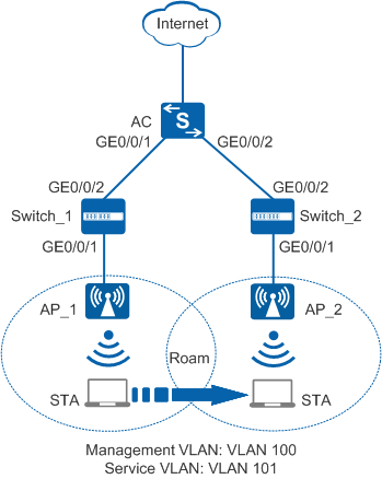
As shown in Figure 1, an AC provides services for the employees. It connects to AP_1 and AP_2 through Switch_1 and Switch_2 respectively.
Data planning
Item |
Data |
|---|---|
DHCP server |
The AC functions as a DHCP server to assign IP addresses to the STAs and APs. |
IP address pool for the APs |
10.23.100.2-10.23.100.254/24 |
IP address pool for the STAs |
10.23.101.2-10.23.101.254/24 |
AC's source interface address |
VLANIF 100: 10.23.100.1/24 |
AP group |
|
Regulatory domain profile |
|
SSID profile |
|
Security profile |
|
VAP profile |
|
Configuration Roadmap
- Configure parameters used for communication between the AC and APs to transmit CAPWAP packets.
- Configure the AC to function as a DHCP server to assign IP addresses to the STAs and APs.
- Configure basic WLAN services so that users can connect to the wireless network.
Procedure
- Configure the switches and the AC so that the AC can communicate with the APs.# On Switch_1, create VLAN 100 (management VLAN). Add GE0/0/1 connected to AP_1 and GE0/0/2 connected to AC to VLAN 100.
<HUAWEI> system-view
[HUAWEI] sysname Switch_1
[Switch_1] vlan batch 100
[Switch_1] interface gigabitethernet 0/0/1
[Switch_1-GigabitEthernet0/0/1] port link-type trunk
[Switch_1-GigabitEthernet0/0/1] port trunk pvid vlan 100
[Switch_1-GigabitEthernet0/0/1] port trunk allow-pass vlan 100
[Switch_1-GigabitEthernet0/0/1] undo port trunk allow-pass vlan 1
[Switch_1-GigabitEthernet0/0/1] stp edged-port enable
[Switch_1-GigabitEthernet0/0/1] port-isolate enable
[Switch_1-GigabitEthernet0/0/1] quit
[Switch_1] interface gigabitethernet 0/0/2
[Switch_1-GigabitEthernet0/0/2] port link-type trunk
[Switch_1-GigabitEthernet0/0/2] port trunk allow-pass vlan 100
[Switch_1-GigabitEthernet0/0/2] undo port trunk allow-pass vlan 1
[Switch_1-GigabitEthernet0/0/2] quit
# On Switch_2, create VLAN 100 (management VLAN). Add GE0/0/1 connected to AP_2 and GE0/0/2 connected to AC to VLAN 100.<HUAWEI> system-view [HUAWEI] sysname Switch_2 [Switch_2] vlan batch 100 [Switch_2] interface gigabitethernet 0/0/1 [Switch_2-GigabitEthernet0/0/1] port link-type trunk [Switch_2-GigabitEthernet0/0/1] port trunk pvid vlan 100 [Switch_2-GigabitEthernet0/0/1] port trunk allow-pass vlan 100 [Switch_2-GigabitEthernet0/0/1] undo port trunk allow-pass vlan 1 [Switch_2-GigabitEthernet0/0/1] stp edged-port enable [Switch_2-GigabitEthernet0/0/1] port-isolate enable [Switch_2-GigabitEthernet0/0/1] quit [Switch_2] interface gigabitethernet 0/0/2 [Switch_2-GigabitEthernet0/0/2] port link-type trunk [Switch_2-GigabitEthernet0/0/2] port trunk allow-pass vlan 100 [Switch_2-GigabitEthernet0/0/2] undo port trunk allow-pass vlan 1 [Switch_2-GigabitEthernet0/0/2] quit
# On the AC, add GE0/0/1 connected to Switch_1 and GE0/0/2 connected to Switch_2 to VLAN 100.<HUAWEI> system-view [HUAWEI] sysname AC [AC] vlan batch 100 to 102 [AC] interface gigabitethernet 0/0/1 [AC-GigabitEthernet0/0/1] port link-type trunk [AC-GigabitEthernet0/0/1] port trunk allow-pass vlan 100 [AC-GigabitEthernet0/0/1] undo port trunk allow-pass vlan 1 [AC-GigabitEthernet0/0/1] quit [AC] interface gigabitethernet 0/0/2 [AC-GigabitEthernet0/0/2] port link-type trunk [AC-GigabitEthernet0/0/2] port trunk allow-pass vlan 100 [AC-GigabitEthernet0/0/2] undo port trunk allow-pass vlan 1 [AC-GigabitEthernet0/0/2] quit
- Configure the AC as a DHCP server to assign IP addresses to STAs and APs.
# Configure the AC as a DHCP server based on interface address pools. Configure VLANIF 100 to assign IP addresses to APs and VLANIF 101 to assign IP addresses to STAs.
 Configure the DNS server as required. The common methods are as follows:
- In interface address pool scenarios, run the dhcp server dns-list ip-address &<1-8> command in the VLANIF interface view.
- In global address pool scenarios, run the dns-list ip-address &<1-8> command in the IP address pool view.
[AC] dhcp enable
[AC] interface vlanif 100
[AC-Vlanif100] ip address 10.23.100.1 255.255.255.0
[AC-Vlanif100] dhcp select interface
[AC-Vlanif100] quit
[AC] interface vlanif 101
[AC-Vlanif101] ip address 10.23.101.1 255.255.255.0
[AC-Vlanif101] dhcp select interface
[AC-Vlanif101] quit
- Configure the APs to go online.
# Create an AP group.
[AC] wlan
[AC-wlan-view] ap-group name ap-group1
[AC-wlan-ap-group-ap-group1] quit
# Create a regulatory domain profile, configure the AC country code in the profile, and apply the profile to the AP group.
[AC-wlan-view] regulatory-domain-profile name domain
[AC-wlan-regulate-domain-domain] country-code cn
[AC-wlan-regulate-domain-domain] quit
[AC-wlan-view] ap-group name ap-group1
[AC-wlan-ap-group-ap-group1] regulatory-domain-profile domain
Warning: Modifying the country code will clear channel, power and antenna gain configurations of the radio and reset the AP. Continue?[Y/N]:y
[AC-wlan-ap-group-ap-group1] quit
# Configure the AC's source interface.
[AC] capwap source interface vlanif 100
# Import APs offline on the AC and add APs to AP group ap-group1. Assume that the type of AP_1 and AP_2 is AP6010DN-AGN, and their MAC addresses are 60de-4476-e360 and dcd2-fc04-b500, respectively. The default AP authentication mode is MAC address authentication. If the default settings are retained, you do not need to run the ap auth-mode mac-auth command.
In this example, the AP6010DN-AGN is used and has two radios: radio 0 and radio 1.
[AC] wlan
[AC-wlan-view] ap auth-mode mac-auth
[AC-wlan-view] ap-id 0 ap-mac 60de-4476-e360
[AC-wlan-ap-0] ap-name ap1
[AC-wlan-ap-0] ap-group ap-group1
Warning: This operation may cause AP reset. If the country code changes, it will clear channel, power and antenna gain configuration s of the radio, Whether to continue? [Y/N]:y
[AC-wlan-ap-0] quit
[AC-wlan-view] ap-id 1 ap-mac dcd2-fc04-b500
[AC-wlan-ap-1] ap-name ap2
[AC-wlan-ap-1] ap-group ap-group1
Warning: This operation may cause AP reset. If the country code changes, it will clear channel, power and antenna gain configuration s of the radio, Whether to continue? [Y/N]:y
[AC-wlan-ap-1] quit
# Power on the APs and run the display ap all command to check the AP state. If the State field is nor, the APs have gone online.
[AC-wlan-view] display ap all
Total AP information:
nor  : normal          [2]
--------------------------------------------------------------------------------------
ID   MAC            Name      Group     IP            Type            State STA Uptime
--------------------------------------------------------------------------------------
0    60de-4476-e360 ap1       ap-group1 10.23.100.254 AP6010DN-AGN    nor   0   15S
1    dcd2-fc04-b500 ap2       ap-group1 10.23.100.253 AP6010DN-AGN    nor   0   10S
--------------------------------------------------------------------------------------
Total: 2
- Configure basic WLAN services on the AC.# Create security profile wlan-security and set the security policy in the profile.
In this example, the security policy is set to WPA2+PSK+AES and password to a1234567. In actual situations, the security policy must be configured according to service requirements.
[AC-wlan-view] security-profile name wlan-security
[AC-wlan-sec-prof-wlan-security] security wpa2 psk pass-phrase a1234567 aes
[AC-wlan-sec-prof-wlan-security] quit
# Create SSID profile wlan-ssid and set the SSID name to wlan-net.
[AC-wlan-view] ssid-profile name wlan-ssid
[AC-wlan-ssid-prof-wlan-ssid] ssid wlan-net
[AC-wlan-ssid-prof-wlan-ssid] quit
# Create VAP profiles wlan-vap1, set the data forwarding mode and service VLANs, and apply the security profile wlan-security and SSID profile wlan-ssid to the VAP profiles.
[AC-wlan-view] vap-profile name wlan-vap1
[AC-wlan-vap-prof-wlan-vap1] forward-mode tunnel
[AC-wlan-vap-prof-wlan-vap1] service-vlan vlan-id 101
[AC-wlan-vap-prof-wlan-vap1] security-profile wlan-security
[AC-wlan-vap-prof-wlan-vap1] ssid-profile wlan-ssid
[AC-wlan-vap-prof-wlan-vap1] quit
# Bind VAP profile wlan-vap1 to AP group ap-group1, and apply the VAP profiles to radio 0 and radio 1 of the APs.
[AC-wlan-view] ap-group name ap-group1
[AC-wlan-ap-group-ap-group1] vap-profile wlan-vap1 wlan 1 radio 0
[AC-wlan-ap-group-ap-group1] vap-profile wlan-vap1 wlan 1 radio 1
[AC-wlan-ap-group-ap-group1] quit
- Commit the configuration.
[AC-wlan-view] commit all
Warning: Committing configuration may cause service interruption, continue?[Y/N]:y
- Verify the configuration.The AC automatically delivers WLAN service configuration to the APs. After the service configuration is complete, run the display vap ssid wlan-net command to check VAP information. In the command output, if Status is ON, the VAPs have been successfully created on AP radios.
[AC-wlan-view] display vap ssid wlan-net
WID : WLAN ID
--------------------------------------------------------------------------------------
AP ID AP name        RfID WID  BSSID          Status  Auth type         STA    SSID
--------------------------------------------------------------------------------------
0     ap1            0    1    60DE-4476-E360 ON      WPA2-PSK          0      wlan-net
0     ap1            1    1    60DE-4476-E370 ON      WPA2-PSK          0      wlan-net
0     ap2            0    1    DCD2-FC04-B500 ON      WPA2-PSK          0      wlan-net
0     ap2            1    1    DCD2-FC04-B510 ON      WPA2-PSK          0      wlan-net
---------------------------------------------------------------------------------------
Total: 2
In the coverage area of AP_1, connect the STA to the wireless network with SSID wlan-net and enter the password a1234567. After the STA successfully associates with the network, run the display station ssid wlan-net command on the AC. The command output shows that the STA with MAC address e019-1dc7-1e08 has associated with AP_1.[AC-wlan-view] display station ssid wlan-net Rf/WLAN: Radio ID/WLAN ID Rx/Tx: link receive rate/link transmit rate(Mbps) ------------------------------------------------------------------------------------ STA MAC AP ID Ap name Rf/WLAN Band Type Rx/Tx RSSI VLAN IP address ------------------------------------------------------------------------------------ e019-1dc7-1e08 0 ap1 1/1 5G 11n 46/59 -57 101 10.23.101.254 ------------------------------------------------------------------------------------ Total: 1 2.4G: 0 5G: 1
After the STA moves from the coverage area of AP_1 to that of AP_2, run the display station ssid wlan-net command on AC. The command output shows that the STA has associated with AP_2.[AC-wlan-view] display station ssid wlan-net Rf/WLAN: Radio ID/WLAN ID Rx/Tx: link receive rate/link transmit rate(Mbps) ------------------------------------------------------------------------------------ STA MAC AP ID Ap name Rf/WLAN Band Type Rx/Tx RSSI VLAN IP address ------------------------------------------------------------------------------------ e019-1dc7-1e08 1 ap2 1/1 5G 11n 46/59 -58 101 10.23.101.254 ------------------------------------------------------------------------------------ Total: 1 2.4G: 0 5G: 1
Run the display station roam-track sta-mac e019-1dc7-1e08 command on AC to check the STA roaming track.[AC-wlan-view] display station roam-track sta-mac e019-1dc7-1e08 Access SSID:wlan-net Rx/Tx: link receive rate/link transmit rate(Mbps) ------------------------------------------------------------------------------ L2/L3 AC IP AP name Radio ID BSSID TIME In/Out RSSI Out Rx/Tx ------------------------------------------------------------------------------ -- 10.23.100.1 ap1 1 60de-4476-e360 2016/02/07 17:48:30 -57/-58 46/65 L2 10.23.100.1 ap2 1 dcd2-fc04-b500 2016/02/07 17:54:50 -58/- -/- ------------------------------------------------------------------------------ Number: 1
Configuration Files
Switch_1 configuration file
#
 sysname Switch_1
#
 vlan batch 100
#
interface GigabitEthernet0/0/1
 port link-type trunk
 port trunk pvid vlan 100
 undo port trunk allow-pass vlan 1
 port trunk allow-pass vlan 100
 stp edged-port enable
 port-isolate enable group 1
#
interface GigabitEthernet0/0/2
 port link-type trunk
 undo port trunk allow-pass vlan 1
 port trunk allow-pass vlan 100
 #
return
Switch_2 configuration file
#
 sysname Switch_2
#
 vlan batch 100
#
interface GigabitEthernet0/0/1
 port link-type trunk
 port trunk pvid vlan 100
 undo port trunk allow-pass vlan 1
 port trunk allow-pass vlan 100
 stp edged-port enable
 port-isolate enable group 1
#
interface GigabitEthernet0/0/2
 port link-type trunk
 undo port trunk allow-pass vlan 1
 port trunk allow-pass vlan 100
 #
return
AC configuration file
#
 sysname AC
#
vlan batch 100 to 102
#
dhcp enable
#
interface Vlanif100
 ip address 10.23.100.1 255.255.255.0
 dhcp select interface
#
interface Vlanif101
 ip address 10.23.101.1 255.255.255.0
 dhcp select interface
#
interface GigabitEthernet0/0/1
 port link-type trunk
 undo port trunk allow-pass vlan 1
 port trunk allow-pass vlan 100
#
interface GigabitEthernet0/0/2
 port link-type trunk
 undo port trunk allow-pass vlan 1
 port trunk allow-pass vlan 100
#
capwap source interface vlanif100
#
wlan
 security-profile name wlan-security
  security wpa2 psk pass-phrase %^%#]:krYrz_r<ee}|Cq@9V(W{ZD$"\-R-HD_y.4#U4,%^%# aes
 ssid-profile name wlan-ssid
  ssid wlan-net
 vap-profile name wlan-vap1
  forward-mode tunnel
  service-vlan vlan-id 101
  ssid-profile wlan-ssid
  security-profile wlan-security
 regulatory-domain-profile name domain
 ap-group name ap-group1
  regulatory-domain-profile domain
  radio 0
   vap-profile wlan-vap1 wlan 1
  radio 1
   vap-profile wlan-vap1 wlan 1
 ap-id 0 ap-mac 60de-4476-e360
  ap-name ap1
  ap-group ap-group1
 ap-id 1 ap-mac dcd2-fc04-b500
  ap-name ap2
  ap-group ap-group1
#
return