Example for Configuring Fast Roaming Between APs in Different Service VLANs
Roaming Between APs in Different Service VLANs Overview
WLAN roaming allows a STA to move from the coverage area of an AP to that of another AP with nonstop service transmission. In roaming between APs in different service VLANs, APs before and after STA roaming belong to different service VLANs. To prevent services of a user from being interrupted during WLAN roaming, ensure that the service VLAN of the user remains unchanged after the user roams between two APs.
Roaming between APs in the same service VLAN is classified into fast roaming and non-fast roaming. Non-fast roaming technology is used when a STA uses a non-WPA2-802.1X security policy. If a STA uses WPA2-802.1X but does not support fast roaming, the STA still needs to complete 802.1X authentication before roaming between two APs. When the user uses the WPA2-802.1X security policy and supports fast roaming, the user does not need to perform 802.1X authentication again during roaming and only needs to perform key negotiation. In this case, fast roaming reduces the roaming delay and improves the WLAN service experience.
Configuration Notes
- The APs on which WLAN roaming is implemented must use the same SSID and security profiles, and the security profiles must have the same configurations.
In direct forwarding mode, if the ARP entry of a user is not aged out in time on the access device connected to the AP after the user roams, services of the user will be temporarily interrupted. You are advised to enable STA address learning on the AC. After the function is enabled, the AP will send a gratuitous ARP packet to the access device so that the access device can update ARP entries in a timely manner. This ensures nonstop service transmission during user roaming.
You can use either of the following methods to enable STA address learning according to the version of your product:- Versions earlier than V200R007C20 and V200R008: run the learn client ip-address enable command in the service set view.
- V200R007C20: run the undo learn-client-address disable command in the VAP profile view.
In direct forwarding mode, configure port isolation on the interface directly connected to APs. If port isolation is not configured, many broadcast packets will be transmitted in the VLANs or WLAN users on different APs can directly communicate at Layer 2.
- No ACK mechanism is provided for multicast packet transmission on air interfaces. In addition, wireless links are unstable. To ensure stable transmission of multicast packets, they are usually sent at low rates. If a large number of such multicast packets are sent from the network side, the air interfaces may be congested. You are advised to configure multicast packet suppression to reduce impact of a large number of low-rate multicast packets on the wireless network. Exercise caution when configuring the rate limit; otherwise, the multicast services may be affected.
- In direct forwarding mode, you are advised to configure multicast packet suppression on switch interfaces connected to APs.
- In tunnel forwarding mode, you are advised to configure multicast packet suppression in traffic profiles of the AC.
- The following table lists applicable products and versions.
Table 1 Applicable products and versions Software Version
Product Model
AP Model and Version
V200R005C00
S7700, S9700
V200R005C00:
AP2010DN, AP3010DN-AGN, AP5010DN-AGN, AP5010SN-GN, AP5030DN, AP5130DN, AP6010SN-GN, AP6010DN-AGN, AP6310SN-GN, AP6510DN-AGN, AP6610DN-AGN, AP7110DN-AGN, AP7110SN-GN
V200R006C00
S5720-HI, S7700, S9700
V200R005C00:
AP2010DN, AP3010DN-AGN, AP5010DN-AGN, AP5010SN-GN, AP5030DN, AP5130DN, AP6010SN-GN, AP6010DN-AGN, AP6310SN-GN, AP6510DN-AGN, AP6610DN-AGN, AP7110DN-AGN, AP7110SN-GN
V200R007C00
S5720-HI, S7700, S9700
V200R005C10:
AP2010DN, AP3010DN-AGN, AP5010DN-AGN, AP5010SN-GN, AP5030DN, AP5130DN, AP6010SN-GN, AP6010DN-AGN, AP6310SN-GN, AP6510DN-AGN, AP6610DN-AGN, AP7110DN-AGN, AP7110SN-GN, AP8030DN, AP8130DN
V200R005C20:
AP7030DE, AP9330DN
V200R008C00
S5720-HI, S7700, S9700
V200R005C10:
AP2010DN, AP3010DN-AGN, AP5010DN-AGN, AP5010SN-GN, AP5030DN, AP5130DN, AP6010SN-GN, AP6010DN-AGN, AP6310SN-GN, AP6510DN-AGN, AP6610DN-AGN, AP7110DN-AGN, AP7110SN-GN, AP8030DN, AP8130DN
V200R005C20:
AP7030DE, AP9330DN
V200R005C30:
AP2030DN, AP4030DN, AP4130DN

For S7700, you are advised to deploy S7712 or S7706 switches for WLAN services. S7703 switches are not recommended.
For S9700, you are advised to deploy S9712 or S9706 switches for WLAN services. S9703 switches are not recommended.
Networking Requirements
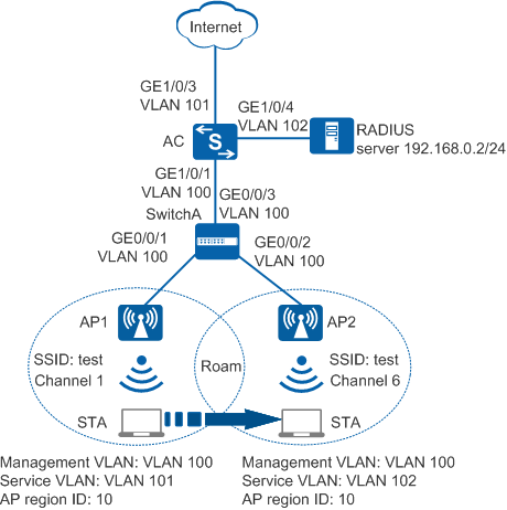
As shown in Figure 1, two APs are deployed in a campus network to provide WLAN services for employees of two departments, and are managed and controlled by an AC. The AC dynamically assigns IP addresses to the APs and STAs. The employees of the two departments belong to different VLANs, that is, AP1 belongs to VLAN101 and AP2 belongs to VLAN102. The security policy WPA2-802.1X is used. User data is forwarded through tunnels.
The department requires that services should not be interrupted when a STA moves from AP1 to AP2.
Data Planning
Item |
Data |
Description |
|---|---|---|
IP address of the AC's source interface |
192.168.10.1/24 |
None |
WMM profile |
Name: wmm |
None |
Radio profile |
Name: radio |
None |
Security profile |
|
None |
Traffic profile |
Name: traffic |
None |
Service set |
|
None |
|
None |
|
DHCP server |
The AC functions as the DHCP server to assign IP addresses to APs and STAs. |
None |
AP gateway and IP address pool range |
VLANIF 100: 192.168.10.1/24 192.168.10.2 to 192.168.10.254/24 |
None |
STA gateway and IP address pool range |
VLANIF 101: 192.168.11.1/24 192.168.11.2 to 192.168.11.254/24 |
None |
VLANIF 102: 192.168.121.1/24 192.168.12.2 to 192.168.12.254/24 |
None |
Configuration Roadmap
- The security policy WPA2-802.1X is used and access authentication is required, which results in longer roaming switchover time. Configure fast roaming between APs in the same service VLAN to ensure nonstop service transmission during roaming.
- Configure parameters used for communication between the AC and APs to transmit CAPWAP packets.
- Configure the AC as a DHCP server to assign IP addresses to the STAs and APs.
- Configure basic WLAN services to enable the STAs to connect to the WLAN.
- Configure key negotiation between STAs and APs to shorten the roaming switchover time.
Procedure
- Set the NAC mode on AC
to unified mode (default setting). Configure SwitchA and the AC to
allow the APs and AC to transmit CAPWAP packets.
# Configure the SwitchA: add interfaces GE0/0/1, GE0/0/2, and GE0/0/3 to the management VLAN 100.
<HUAWEI> system-view
[HUAWEI] sysname SwitchA
[SwitchA] vlan batch 100
[SwitchA] interface gigabitethernet 0/0/1
[SwitchA-GigabitEthernet0/0/1] port link-type trunk
[SwitchA-GigabitEthernet0/0/1] port trunk pvid vlan 100
[SwitchA-GigabitEthernet0/0/1] port trunk allow-pass vlan 100
[SwitchA-GigabitEthernet0/0/1] quit
[SwitchA] interface gigabitethernet 0/0/2
[SwitchA-GigabitEthernet0/0/2] port link-type trunk
[SwitchA-GigabitEthernet0/0/2] port trunk pvid vlan 100
[SwitchA-GigabitEthernet0/0/2] port trunk allow-pass vlan 100
[SwitchA-GigabitEthernet0/0/2] quit
[SwitchA] interface gigabitethernet 0/0/3
[SwitchA-GigabitEthernet0/0/3] port link-type trunk
[SwitchA-GigabitEthernet0/0/3] port trunk allow-pass vlan 100
[SwitchA-GigabitEthernet0/0/3] quit
# Add GE1/0/1 that connects the AC to SwitchA to VLAN 100.
<HUAWEI> system-view
[HUAWEI] sysname AC
[AC] vlan batch 100
[AC] interface gigabitethernet 1/0/1
[AC-GigabitEthernet1/0/1] port link-type trunk
[AC-GigabitEthernet1/0/1] port trunk allow-pass vlan 100
[AC-GigabitEthernet1/0/1] quit
- Connect the AC to the upper-level network device.
# Add the AC uplink interface GE1/0/3 to VLAN 101 and VLAN 102, and add GE1/0/4 of the AC connecting to the RADIUS server to VLAN 103.
[AC] vlan batch 101 to 103
[AC] interface gigabitethernet 1/0/3
[AC-GigabitEthernet1/0/3] port link-type trunk
[AC-GigabitEthernet1/0/3] port trunk allow-pass vlan 101 102
[AC-GigabitEthernet1/0/3] quit
[AC] interface gigabitethernet 1/0/4
[AC-GigabitEthernet1/0/4] port link-type trunk
[AC-GigabitEthernet1/0/4] port trunk pvid vlan 103
[AC-GigabitEthernet1/0/4] port trunk allow-pass vlan 103
[AC-GigabitEthernet1/0/4] quit
- Configure the AC to function as a DHCP server to assign IP addresses to the STAs and APs, and configure VLANIF 103 to allow the AC to communicate with the RADIUS server.
# Configure the DHCP server based on the interface address pool. VLANIF100 provides IP addresses for AP1 and AP2, VLANIF101 provides IP addresses for STAs connected to AP1, and VLANIF102 provides IP addresses for STAs connected to AP2.
[AC] dhcp enable  //Enable the DHCP function.
[AC] interface vlanif 100
[AC-Vlanif100] ip address 192.168.10.1 24
[AC-Vlanif100] dhcp select interface  //Configure an interface-based address pool.
[AC-Vlanif100] quit
[AC] interface vlanif 101
[AC-Vlanif101] ip address 192.168.11.1 24
[AC-Vlanif101] dhcp select interface
[AC-Vlanif101] quit
[AC] interface vlanif 102
[AC-Vlanif102] ip address 192.168.12.1 24
[AC-Vlanif102] dhcp select interface
[AC-Vlanif102] quit
# Configure VLANIF 103.
[AC] interface vlanif 103
[AC-Vlanif103] ip address 192.168.0.1 24
[AC-Vlanif103] quit
- Configure an AAA domain to which a RADIUS server template is applied.
- Configure a RADIUS server template, an AAA authentication scheme, and domain information.
Ensure that the AC and RADIUS server have the same shared key.
[AC] radius-server template radius_huawei  //Creates a RADIUS server template
[AC-radius-radius_huawei] radius-server authentication 192.168.0.2 1812  //Specify the IP address and the port number of a RADIUS authentication server.
[AC-radius-radius_huawei] radius-server shared-key cipher hello  //Configure the shared key of a RADIUS server
[AC-radius-radius_huawei] quit
[AC] aaa
[AC-aaa] authentication-scheme radius_huawei  //Create an authentication scheme
[AC-aaa-authen-radius_huawei] authentication-mode radius  //Set the authentication mode to radius.
[AC-aaa-authen-radius_huawei] quit
[AC-aaa] domain huawei.com  //Create a domain
[AC-aaa-domain-huawei.com] authentication-scheme radius_huawei  //Configure an authentication scheme in the domain.
[AC-aaa-domain-huawei.com] radius-server radius_huawei  //Configure a RADIUS server template for the domain.
[AC-aaa-domain-huawei.com] quit
[AC-aaa] quit
After domain huawei.com is configured, the domain name is added to the authentication user name.
- Configure a RADIUS server template, an AAA authentication scheme, and domain information.
- Configure AC system parameters.
# Configure the country code.
[AC] wlan ac-global country-code cn
Warning: Modify the country code may delete configuration on those AP which use
the global country code and reset them, continue?[Y/N]:y
# Configure the AC ID and carrier ID.
[AC] wlan ac-global ac id 1 carrier id other //The default AC ID is 0. Set the AC ID to 1.# Configure the source interface.
[AC] wlan
[AC-wlan-view] wlan ac source interface vlanif 100
- Manage APs on the AC.
# Check the AP type IDs after obtaining the MAC addresses of the APs.
[AC-wlan-view] display ap-type all
  All AP types information:
  ------------------------------------------------------------------------------
  ID     Type
  ------------------------------------------------------------------------------
  17     AP6010SN-GN
  19     AP6010DN-AGN
  21     AP6310SN-GN
  23     AP6510DN-AGN
  25     AP6610DN-AGN
  27     AP7110SN-GN
  28     AP7110DN-AGN
  29     AP5010SN-GN
  30     AP5010DN-AGN
  31     AP3010DN-AGN
  33     AP6510DN-AGN-US
  34     AP6610DN-AGN-US
  35     AP5030DN
  36     AP5130DN
  37     AP7030DE
  38     AP2010DN
  39     AP8130DN
  40     AP8030DN
  42     AP9330DN
  43     AP4030DN
  44     AP4130DN
  45     AP3030DN
  46     AP2030DN
  ------------------------------------------------------------------------------
  Total number: 23
# Set the AP authentication mode to MAC address authentication (default setting). Add the APs offline based on the AP type ID. Assume that the type of AP1 and AP2 is AP6010DN-AGN, and their MAC addresses are 60de-4476-e360 and dcd2-fc04-b500, respectively.
[AC-wlan-view] ap id 1 type-id 19 mac 60de-4476-e360
[AC-wlan-ap-1] quit
[AC-wlan-view] ap id 2 type-id 19 mac dcd2-fc04-b500
[AC-wlan-ap-2] quit
# Configure an AP region and add the APs to the AP region.
[AC-wlan-view] ap-region id 10  //Create AP region 10
[AC-wlan-ap-region-10] quit
[AC-wlan-view] ap id 1
[AC-wlan-ap-1] region-id 10  //Add AP1 to region 10
[AC-wlan-ap-1] quit
[AC-wlan-view] ap id 2
[AC-wlan-ap-2] region-id 10  //Add AP2 to region 10
[AC-wlan-ap-2] quit
# Power on AP1 and AP2 and run the display ap all command on the AC to check the AP state. The command output shows that the APs are in normal state.
[AC-wlan-view] display ap all All AP information: Normal[2],Fault[0],Commit-failed[0],Committing[0],Config[0],Download[0] Config-failed[0],Standby[0],Type-not-match[0],Ver-mismatch[0] ------------------------------------------------------------------------------ AP AP AP Profile AP AP /Region ID Type MAC ID State Sysname ------------------------------------------------------------------------------ 1 AP6010DN-AGN 60de-4476-e360 0/10 normal ap-1 2 AP6010DN-AGN dcd2-fc04-b500 0/10 normal ap-2 ------------------------------------------------------------------------------ Total number: 2,printed: 2 - Configure WLAN service parameters.
# Create a WMM profile named wmm and retain the default parameter settings.
[AC-wlan-view] wmm-profile name wmm id 1
[AC-wlan-wmm-prof-wmm] quit
# Create a radio profile named radio and bind the WMM profile wmm to the radio profile.
[AC-wlan-view] radio-profile name radio id 1
[AC-wlan-radio-prof-radio] channel-mode fixed
[AC-wlan-radio-prof-radio] wmm-profile name wmm
[AC-wlan-radio-prof-radio] quit
[AC-wlan-view] quit
# Create a WLAN-ESS interface. To implement roaming between APs in different service VLANs, configure two service VLANs (VLAN101 and VLAN102) on each WLAN-ESS interface.
[AC] interface wlan-ess 0
[AC-Wlan-Ess0] port trunk allow-pass vlan 101 102
[AC-Wlan-Ess0] authentication dot1x   //Enable 802.1X authentication.
[AC-Wlan-Ess0] dot1x authentication-method eap  //Configure EAP relay authentication for 802.1X users.
[AC-Wlan-Ess0] domain name huawei.com force  //Configure a forcible authentication domain.
[AC-Wlan-Ess0] permit-domain name huawei.com  //Configure a permitted domain for WLAN users.
[AC-Wlan-Ess0] quit
[AC] interface wlan-ess 1
[AC-Wlan-Ess1] port trunk allow-pass vlan 101 102
[AC-Wlan-Ess1] authentication dot1x
[AC-Wlan-Ess1] dot1x authentication-method eap
[AC-Wlan-Ess1] domain name huawei.com force
[AC-Wlan-Ess1] permit-domain name huawei.com
[AC-Wlan-Ess1] quit
# Create a security profile named security and configure the security policy to WPA2-802.1X.
[AC] wlan
[AC-wlan-view] security-profile name security id 1
[AC-wlan-sec-prof-security] security-policy wpa2
[AC-wlan-sec-prof-security] wpa2 authentication-method dot1x encryption-method ccmp  //Configure WPA2 802.1X authentication and encryption.
[AC-wlan-sec-prof-security] quit
# Create a traffic profile named traffic and retain the default parameter settings.
[AC-wlan-view] traffic-profile name traffic id 1
[AC-wlan-traffic-prof-traffic] quit
# Configure service sets for AP1 and AP2, and set the data forwarding mode to tunnel forwarding.
[AC-wlan-view] service-set name huawei-1
[AC-wlan-service-set-huawei-1] ssid test
[AC-wlan-service-set-huawei-1] wlan-ess 0
[AC-wlan-service-set-huawei-1] service-vlan 101
[AC-wlan-service-set-huawei-1] security-profile name security
[AC-wlan-service-set-huawei-1] traffic-profile name traffic
[AC-wlan-service-set-huawei-1] forward-mode tunnel
[AC-wlan-service-set-huawei-1] quit
[AC-wlan-view] service-set name huawei-2
[AC-wlan-service-set-huawei-2] ssid test
[AC-wlan-service-set-huawei-2] wlan-ess 1
[AC-wlan-service-set-huawei-2] service-vlan 102
[AC-wlan-service-set-huawei-2] security-profile name security
[AC-wlan-service-set-huawei-2] traffic-profile name traffic
[AC-wlan-service-set-huawei-2] forward-mode tunnel
[AC-wlan-service-set-huawei-2] quit
# Configure a VAP.
[AC-wlan-view] ap 1 radio 0
[AC-wlan-radio-1/0] radio-profile name radio
[AC-wlan-radio-1/0] channel 20mhz 1
[AC-wlan-radio-1/0] service-set name huawei-1
[AC-wlan-radio-1/0] quit
[AC-wlan-view] ap 2 radio 0
[AC-wlan-radio-2/0] radio-profile name radio
[AC-wlan-radio-2/0] channel 20mhz 6
[AC-wlan-radio-2/0] service-set name huawei-2
[AC-wlan-radio-2/0] quit
# Commit the configuration.
[AC-wlan-view] commit ap 1
  Warning: Committing configuration may cause service interruption, continue?[Y/N]y
[AC-wlan-view] commit ap 2
  Warning: Committing configuration may cause service interruption, continue?[Y/N]y
- Verify the configuration.
After the configuration is complete, the STA can connect to the WLAN with the SSID test in the coverage area of AP1. Use 802.1X authentication on the STA and enter the user name and password. If the authentication succeeds, the STA can connect to the Internet. Configure the STA according to the configured authentication mode PEAP.
Configuration on the Windows 7 operating system:
- Access the Manage wireless networks page, click Add, and select Manually create a network profile. Add SSID test. Set the authentication mode to WPA2-Enterprise, the encryption mode to CCMP, and the algorithm to AES. Click Next.
- Scan SSIDs and double-click SSID test. On the Security tab page, set EAP type to PEAP and click Settings. In the displayed dialog box, deselect Validate server certificate and click Configure. In the displayed dialog box, deselect Automatically use my Windows logon name and password and click OK.
Assume that the STA MAC address is 0025-86aa-0d1c. When the STA connects to the WLAN with the SSID test in the coverage area of AP1, run the display station assoc-info ap 1 command on the AC to check the STA access information.<HUAWEI> display station assoc-info ap 1 ------------------------------------------------------------------------------ STA MAC AP ID RADIO ID SS ID SSID ------------------------------------------------------------------------------ 0025-86aa-0d1c 1 0 0 test ------------------------------------------------------------------------------ Total stations: 1
When the STA moves from the coverage of AP1 to that of AP2, run the display station assoc-info ap 2 command on the AC to check the STA access information. The STA is associated with AP2.<HUAWEI> display station assoc-info ap 2 ------------------------------------------------------------------------------ STA MAC AP ID RADIO ID SS ID SSID ------------------------------------------------------------------------------ 0025-86aa-0d1c 2 0 1 test ------------------------------------------------------------------------------ Total stations: 1
Run the display station roam-track sta 0025-86aa-0d1c command on the AC to check the STA roaming track.<HUAWEI> display station roam-track sta 0025-86aa-0d1c ------------------------------------------------------------------------------ AP ID Radio ID BSSID TIME ------------------------------------------------------------------------------ 1 0 60de-4476-e360 2012/12/23 14:40:37 2 0 dcd2-fc04-b500 2012/12/23 14:40:39 ------------------------------------------------------------------------------ Number of roam track: 1
Configuration Files
SwitchA configuration file
#
sysname SwitchA
#
vlan batch 100
#
interface GigabitEthernet0/0/1
 port link-type trunk
 port trunk pvid vlan 100
 port trunk allow-pass vlan 100
#
interface GigabitEthernet0/0/2
 port link-type trunk
 port trunk pvid vlan 100
 port trunk allow-pass vlan 100
#
interface GigabitEthernet0/0/3
 port link-type trunk
 port trunk allow-pass vlan 100
#
return
Configuration file of the AC
#
sysname AC
#
vlan batch 100 to 103
#
wlan ac-global carrier id other ac id 1
#
dhcp enable
#
radius-server template radius_huawei
  radius-server shared-key cipher %@%@xI&d>!p~&X_GJ0~yU/z!,x,J%@%@
  radius-server authentication 192.168.0.2 1812 weight 80
#
aaa
 authentication-scheme radius_huawei
  authentication-mode radius
 domain huawei.com
  authentication-scheme radius_huawei
  radius-server radius_huawei
#
interface Vlanif100
 ip address 192.168.10.1 255.255.255.0
 dhcp select interface
#
interface Vlanif101
 ip address 192.168.11.1 255.255.255.0
 dhcp select interface
#
interface Vlanif102
 ip address 192.168.12.1 255.255.255.0
 dhcp select interface
#
interface Vlanif103
 ip address 192.168.0.1 255.255.255.0
#
interface GigabitEthernet1/0/1
 port link-type trunk
 port trunk pvid vlan 100
 port trunk allow-pass vlan 100
#
interface GigabitEthernet1/0/2
 port link-type trunk
 port trunk pvid vlan 100
 port trunk allow-pass vlan 100
#
interface GigabitEthernet1/0/3
 port link-type trunk
 port trunk allow-pass vlan 101 to 102
#
interface GigabitEthernet1/0/4
 port link-type trunk
 port trunk allow-pass vlan 103
#
interface Wlan-Ess0
 port trunk allow-pass vlan 101 to 102
 authentication dot1x
 dot1x authentication-method eap
 permit-domain name huawei.com
 domain name huawei.com force
#
interface Wlan-Ess1
 port trunk allow-pass vlan 101 to 102
 authentication dot1x
 dot1x authentication-method eap
 permit-domain name huawei.com
 domain name huawei.com force
#
wlan
 wlan ac source interface vlanif100
 ap-region id 10
 ap id 1 type-id 19 mac 60de-4476-e360 sn 190901007618
  region-id 10
 ap id 2 type-id 19 mac dcd2-fc04-b500 sn 190901007619
  region-id 10
 wmm-profile name wmm id 1
 traffic-profile name traffic id 1
 security-profile name security id 1
  security-policy wpa2
 service-set name huawei-1 id 0
  forward-mode tunnel
  wlan-ess 0
  ssid test
  traffic-profile id 1
  security-profile id 1
  service-vlan 101
 service-set name huawei-2 id 1
  forward-mode tunnel
  wlan-ess 1
  ssid test
  traffic-profile id 1
  security-profile id 1
  service-vlan 102
 radio-profile name radio id 1
  channel-mode fixed
  wmm-profile id 1
 ap 1 radio 0
  radio-profile id 1
  service-set id 0 wlan 1
 ap 2 radio 0
  radio-profile id 1
  channel 20MHz 6
  service-set id 1 wlan 2
#
return