Example for Configuring WLAN Services on a Small-Scale Network
Small-Scale WLAN Overview
In this document, a Wireless Local Area Network (WLAN) uses 2.4 GHz or 5 GHz radio as transmission medium. WLANs are widely used due to their low cost, flexibility, scalability, and mobility compared to wired networks.
A small-scale WLAN can be a small campus network independently deployed for a small- or medium-sized enterprise, or a branch network. A small-scale WLAN requires only a few network devices to serve its users.
Configuration Notes
In this example, the security policy is WPA2-PSK-CCMP. To ensure network security, choose an appropriate security policy according to your network configurations.
In tunnel forwarding mode, the management VLAN and service VLAN cannot be the same. If you set the forwarding mode to direct forwarding, you are not advised to configure the management VLAN and service VLAN to be the same.
In direct forwarding mode, configure port isolation on the interface directly connected to APs. If port isolation is not configured, many broadcast packets will be transmitted in the VLANs or WLAN users on different APs can directly communicate at Layer 2.
- Configure the management VLAN and service VLAN:
- In tunnel forwarding mode, service packets are encapsulated in a CAPWAP tunnel and forwarded to the AC. The AC then forwards the packets to the upper-layer network or APs. Service packets and management packets can be forwarded normally only if the network between the AC and APs is added to the management VLAN and the network between the AC and upper-layer network is added to the service VLAN.
- In direct forwarding mode, service packets are not encapsulated into a CAPWAP tunnel, but are directly forwarded to the upper-layer network or APs. Service packets and management packets can be forwarded normally only if the network between the AC and APs is added to the management VLAN and the network between APs and upper-layer network is added to the service VLAN.
- No ACK mechanism is provided for multicast packet transmission on air interfaces. In addition, wireless links are unstable. To ensure stable transmission of multicast packets, they are usually sent at low rates. If a large number of such multicast packets are sent from the network side, the air interfaces may be congested. You are advised to configure multicast packet suppression to reduce impact of a large number of low-rate multicast packets on the wireless network. Exercise caution when configuring the rate limit; otherwise, the multicast services may be affected.
- In direct forwarding mode, you are advised to configure multicast packet suppression on switch interfaces connected to APs.
- In tunnel forwarding mode, you are advised to configure multicast packet suppression in traffic profiles of the AC.
- The following table lists applicable products and versions.
Table 1 Applicable products and versions Software Version
Product Model
AP Model and Version
V200R005C00
S7700, S9700
V200R005C00:
AP2010DN, AP3010DN-AGN, AP5010DN-AGN, AP5010SN-GN, AP5030DN, AP5130DN, AP6010SN-GN, AP6010DN-AGN, AP6310SN-GN, AP6510DN-AGN, AP6610DN-AGN, AP7110DN-AGN, AP7110SN-GN
V200R006C00
S5720-HI, S7700, S9700
V200R005C00:
AP2010DN, AP3010DN-AGN, AP5010DN-AGN, AP5010SN-GN, AP5030DN, AP5130DN, AP6010SN-GN, AP6010DN-AGN, AP6310SN-GN, AP6510DN-AGN, AP6610DN-AGN, AP7110DN-AGN, AP7110SN-GN
V200R007C00
S5720-HI, S7700, S9700
V200R005C10:
AP2010DN, AP3010DN-AGN, AP5010DN-AGN, AP5010SN-GN, AP5030DN, AP5130DN, AP6010SN-GN, AP6010DN-AGN, AP6310SN-GN, AP6510DN-AGN, AP6610DN-AGN, AP7110DN-AGN, AP7110SN-GN, AP8030DN, AP8130DN
V200R005C20:
AP7030DE, AP9330DN
V200R008C00
S5720-HI, S7700, S9700
V200R005C10:
AP2010DN, AP3010DN-AGN, AP5010DN-AGN, AP5010SN-GN, AP5030DN, AP5130DN, AP6010SN-GN, AP6010DN-AGN, AP6310SN-GN, AP6510DN-AGN, AP6610DN-AGN, AP7110DN-AGN, AP7110SN-GN, AP8030DN, AP8130DN
V200R005C20:
AP7030DE, AP9330DN
V200R005C30:
AP2030DN, AP4030DN, AP4130DN

For S7700, you are advised to deploy S7712 or S7706 switches for WLAN services. S7703 switches are not recommended.
For S9700, you are advised to deploy S9712 or S9706 switches for WLAN services. S9703 switches are not recommended.
Networking Requirements
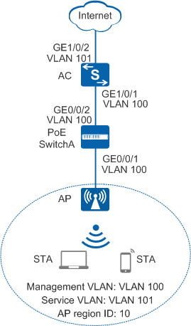
An enterprise has a small-scale branch network. The enterprise needs to deploy WLAN services for mobile office so that its employees can access the enterprise internal network anywhere and anytime.
As shown in Figure 1, the AC connects to APs through a PoE switch, and the PoE switch provides power for APs. The WLAN service is configured on the AC, and delivered to APs.
Data Planning
Item |
Data |
Description |
|---|---|---|
IP address of the AC's source interface |
192.168.10.1/24 |
None |
WMM profile |
Name: wmm |
None |
Radio profile |
Name: radio |
None |
Security profile |
|
None |
Traffic profile |
Name: traffic |
None |
Service set |
|
None |
DHCP server |
The AC functions as the DHCP server to assign IP addresses to the AP and STAs. |
None |
AP gateway and IP address pool range |
VLANIF 100: 192.168.10.1/24 192.168.10.2 to 192.168.10.254/24 |
None |
STA gateway and IP address pool range |
VLANIF 101: 192.168.11.1/24 192.168.11.2 to 192.168.11.254/24 |
None |
Configuration Roadmap
The configuration roadmap is as follows:
- Configure the AP, AC, SwitchA, and upstream device to implement Layer 2 interoperation.
- Configure the AC as a DHCP server to assign IP addresses to STAs and the AP from an IP address pool of an interface.
- Configure AC system parameters, including the country code, AC ID, carrier ID, and source interface used by the AC to communicate with the AP.
- Set the AP authentication mode and add the AP to an AP region.
- Configure a VAP and deliver VAP parameters to the AP so that STAs can access the WLAN.
- Configure a WMM profile and radio profile on the AP, retain the default settings of the WMM profile and radio profile, bind the WMM profile to the radio profile to enable STAs to communicate with the AP.
- Configure a WLAN-ESS interface so that radio packets can be sent to the WLAN service module after reaching the AC.
- Configure a security profile and traffic profile on the AP, retain the default settings of the security profile and traffic profile, configure a service set, bind the WLAN-ESS interface, security profile, and traffic profile to the service set to apply security policies and QoS policies to STAs.
- Configure a VAP and deliver VAP parameters to the AP so that STAs can access the Internet through the WLAN.
Procedure
- Set the NAC mode to unified mode on the AC (default setting). Configure SwitchA and the AC to allow the AP and AC to transmit CAPWAP packets.
# Add GE0/0/1 that connects SwitchA to the AP and GE0/0/2 that connects SwitchA to the AC to the management VLAN 100.
<HUAWEI> system-view
[HUAWEI] sysname SwitchA
[SwitchA] vlan batch 100
[SwitchA] interface gigabitethernet 0/0/1
[SwitchA-GigabitEthernet0/0/1] port link-type trunk
[SwitchA-GigabitEthernet0/0/1] port trunk pvid vlan 100
[SwitchA-GigabitEthernet0/0/1] port trunk allow-pass vlan 100
[SwitchA-GigabitEthernet0/0/1] quit
[SwitchA] interface gigabitethernet 0/0/2
[SwitchA-GigabitEthernet0/0/2] port link-type trunk
[SwitchA-GigabitEthernet0/0/2] port trunk allow-pass vlan 100
[SwitchA-GigabitEthernet0/0/2] quit
# Add GE1/0/1 that connects the AC to SwitchA to VLAN 100.
<HUAWEI> system-view
[HUAWEI] sysname AC
[AC] vlan batch 100 101
[AC] interface gigabitethernet 1/0/1
[AC-GigabitEthernet1/0/1] port link-type trunk
[AC-GigabitEthernet1/0/1] port trunk allow-pass vlan 100
[AC-GigabitEthernet1/0/1] quit
- Configure the AC to communicate with the upstream device.
Configure AC uplink interfaces to transparently transmit service VLAN packets as required and communicate with the upstream device.
# Add AC uplink interface GE1/0/2 to service VLAN 101.
[AC] interface gigabitethernet 1/0/2
[AC-GigabitEthernet1/0/2] port link-type trunk
[AC-GigabitEthernet1/0/2] port trunk allow-pass vlan 101
[AC-GigabitEthernet1/0/2] quit
- Configure the AC as a DHCP server to assign IP addresses to STAs and the AP.
# Configure the AC as the DHCP server to assign an IP address to the AP from the IP address pool on VLANIF 100, and assign IP addresses to STAs from the IP address pool on VLANIF 101.
[AC] dhcp enable //Enable the DHCP function. [AC] interface vlanif 100 [AC-Vlanif100] ip address 192.168.10.1 24 [AC-Vlanif100] dhcp select interface //Configure an interface-based address pool. [AC-Vlanif100] quit [AC] interface vlanif 101 [AC-Vlanif101] ip address 192.168.11.1 24 [AC-Vlanif101] dhcp select interface [AC-Vlanif101] quit - Configure AC system parameters.
# Configure the country code.
[AC] wlan ac-global country-code cn
Warning: Modify the country code may delete configuration on those AP which use
the global country code and reset them, continue?[Y/N]:y
# Configure the AC ID and carrier ID.
[AC] wlan ac-global ac id 1 carrier id other //The default AC ID is 0. Set the AC ID to 1.# Configure the source interface.
[AC] wlan
[AC-wlan-view] wlan ac source interface vlanif 100
- Manage the AP on the AC.
# Check the AP type ID after obtaining the MAC address of the AP.
[AC-wlan-view] display ap-type all
  All AP types information:
  ------------------------------------------------------------------------------
  ID     Type
  ------------------------------------------------------------------------------
  17     AP6010SN-GN
  19     AP6010DN-AGN
  21     AP6310SN-GN
  23     AP6510DN-AGN
  25     AP6610DN-AGN
  27     AP7110SN-GN
  28     AP7110DN-AGN
  29     AP5010SN-GN
  30     AP5010DN-AGN
  31     AP3010DN-AGN
  33     AP6510DN-AGN-US
  34     AP6610DN-AGN-US
  35     AP5030DN
  36     AP5130DN
  37     AP7030DE
  38     AP2010DN
  39     AP8130DN
  40     AP8030DN
  42     AP9330DN
  43     AP4030DN
  44     AP4130DN
  45     AP3030DN
  46     AP2030DN
  ------------------------------------------------------------------------------
  Total number: 23
# Set the AP authentication mode to MAC address authentication (default setting). Add the AP offline based on the AP type ID. Assume that the AP type is AP6010DN-AGN, and the MAC address of the AP is 60de-4476-e360.
[AC-wlan-view] ap id 0 type-id 19 mac 60de-4476-e360
[AC-wlan-ap-0] quit
# Configure an AP region and add the AP to the AP region.
[AC-wlan-view] ap-region id 10  //Create AP region 10.
[AC-wlan-ap-region-10] quit
[AC-wlan-view] ap id 0
[AC-wlan-ap-0] region-id 10  //Add AP to region 10.
[AC-wlan-ap-0] quit
# Power on the APs and run the display ap all command on the AC to check the AP running status. The command output shows that the AP status is normal.
[AC-wlan-view] display ap all All AP information: Normal[1],Fault[0],Commit-failed[0],Committing[0],Config[0],Download[0] Config-failed[0],Standby[0],Type-not-match[0],Ver-mismatch[0] ------------------------------------------------------------------------------ AP AP AP Profile AP AP /Region ID Type MAC ID State Sysname ------------------------------------------------------------------------------ 0 AP6010DN-AGN 60de-4476-e360 0/10 normal ap-0 ------------------------------------------------------------------------------ Total number: 1,printed: 1 - Configure WLAN service parameters.
# Create a WMM profile named wmm.
[AC-wlan-view] wmm-profile name wmm id 1
[AC-wlan-wmm-prof-wmm] quit
# Create a radio profile named radio and bind the WMM profile wmm to the radio profile.
[AC-wlan-view] radio-profile name radio id 1
[AC-wlan-radio-prof-radio] wmm-profile name wmm
[AC-wlan-radio-prof-radio] quit
[AC-wlan-view] quit
# Create WLAN-ESS interface 1.
[AC] interface wlan-ess 1
[AC-Wlan-Ess1] port trunk allow-pass vlan 101
[AC-Wlan-Ess1] quit
# Create a security profile named security.
[AC] wlan
[AC-wlan-view] security-profile name security id 1
[AC-wlan-sec-prof-security] security-policy wpa2  //Configure security policy WPA2.
[AC-wlan-sec-prof-security] wpa2 authentication-method psk pass-phrase cipher huawei123 encryption-method ccmp  //Set the encryption method to PSK+CCMP.
[AC-wlan-sec-prof-security] quit
# Create a traffic profile named traffic.
[AC-wlan-view] traffic-profile name traffic id 1
[AC-wlan-traffic-prof-traffic] quit
# Create a service set named test and bind the WLAN-ESS interface, security profile, and traffic profile to the service set.
[AC-wlan-view] service-set name test id 1
[AC-wlan-service-set-test] ssid test  //Set the SSID to test.
[AC-wlan-service-set-test] wlan-ess 1
[AC-wlan-service-set-test] security-profile name security
[AC-wlan-service-set-test] traffic-profile name traffic
[AC-wlan-service-set-test] service-vlan 101  //Set the VLAN ID to 101. The default VLAN ID is 1.
[AC-wlan-service-set-test] forward-mode tunnel  //Set the service forwarding mode to tunnel.
[AC-wlan-service-set-test] quit
- Configure a VAP and deliver VAP parameters to the AP.
# Configure a VAP.
[AC-wlan-view] ap 0 radio 0
[AC-wlan-radio-0/0] radio-profile name radio  //Bind the radio template to a radio.
[AC-wlan-radio-0/0] service-set name test  //Bind the service set to the radio.
[AC-wlan-radio-0/0] quit
# Commit the configuration.
[AC-wlan-view] commit ap 0 Warning: Committing configuration may cause service interruption, continue?[Y/N]y - Verify the configuration.
After the configuration is complete, run the display vap ap 0 radio 0 command. The command output shows that the VAP has been created.
[AC-wlan-view] display vap ap 0 radio 0
  All VAP Information(Total-1):
  SS: Service-set     BP: Bridge-profile     MP: Mesh-profile
  ----------------------------------------------------------------------
  AP ID  Radio ID  SS ID  BP ID  MP ID  WLAN ID  BSSID           Type
  ----------------------------------------------------------------------
  0      0         1      -      -      1        60DE-4476-E360  service
  ----------------------------------------------------------------------
  Total: 1
When a STA detects the wireless network test and associates with it, the wireless PC is allocated an IP address. You need to enter the pre-shared key to access the wireless network. You can run the display station assoc-info command on the AC. The command output shows that the STAs associate with the WLAN test.
[AC-wlan-view] display station assoc-info ap 0 radio 0
  ------------------------------------------------------------------------------
  STA MAC          AP ID   RADIO ID  SS ID    SSID
  ------------------------------------------------------------------------------
  9021-55dc-3e17   0       0         1        test
  ------------------------------------------------------------------------------
  Total stations: 1
Configuration Files
SwitchA configuration file
#
sysname SwitchA
#
vlan batch 100
#
interface GigabitEthernet0/0/1
 port link-type trunk
 port trunk pvid vlan 100
 port trunk allow-pass vlan 100
#
interface GigabitEthernet0/0/2
 port link-type trunk
 port trunk allow-pass vlan 100
#
return
AC configuration file
#
 sysname AC
#
vlan batch 100 to 101
#
wlan ac-global carrier id other ac id 1
#
dhcp enable
#
interface Vlanif100
 ip address 192.168.10.1 255.255.255.0
 dhcp select interface
#
interface Vlanif101
 ip address 192.168.11.1 255.255.255.0
 dhcp select interface
#
interface GigabitEthernet1/0/1
 port link-type trunk
 port trunk allow-pass vlan 100
#
interface GigabitEthernet1/0/2
 port link-type trunk
 port trunk allow-pass vlan 101
#
interface Wlan-Ess1
 port trunk allow-pass vlan 101
#
wlan
 wlan ac source interface vlanif100
 ap-region id 10
 ap id 0 type-id 19 mac 60de-4476-e360 sn 210235419610CB002287
  region-id 10
 wmm-profile name wmm id 1
 traffic-profile name traffic id 1
 security-profile name security id 1
  security-policy wpa2
  wpa2 authentication-method psk pass-phrase cipher %@%@}PSoXN{buC{{i+L![@/I<|C"%@%@ encryption-method ccmp
 service-set name test id 1
  forward-mode tunnel
  wlan-ess 1
  ssid test
  traffic-profile id 1
  security-profile id 1
  service-vlan 101
 radio-profile name radio id 1
  wmm-profile id 1
 ap 0 radio 0
  radio-profile id 1
  service-set id 1 wlan 1
#
return