Example for Configuring WLAN Services on a Small-Scale Network
Small-Scale WLAN Overview
In this document, a Wireless Local Area Network (WLAN) uses 2.4 GHz or 5 GHz radio as transmission medium. WLANs are widely used due to their low cost, flexibility, scalability, and mobility compared to wired networks.
A small-scale WLAN can be a small campus network independently deployed for a small- or medium-sized enterprise, or a branch network. A small-scale WLAN requires only a few network devices to serve its users.
Configuration Notes
For details about common WLAN configuration notes, see General Precautions for WLAN. For more deployment and configuration suggestions, see Wireless Network Deployment and Configuration Suggestions.
From V200R011C10, WLAN configurations are automatically delivered, without the need of running the commit all command.
In this example, the security policy is WPA2-PSK-AES. To ensure network security, choose an appropriate security policy according to your network configurations.
In tunnel forwarding mode, the management VLAN and service VLAN cannot be the same. If you set the forwarding mode to direct forwarding, you are not advised to configure the management VLAN and service VLAN to be the same.
In direct forwarding mode, configure port isolation on the interface directly connected to APs. If port isolation is not configured, many broadcast packets will be transmitted in the VLANs or WLAN users on different APs can directly communicate at Layer 2.
- Configure the management VLAN and service VLAN:
- In tunnel forwarding mode, service packets are encapsulated in a CAPWAP tunnel and forwarded to the AC. The AC then forwards the packets to the upper-layer network. Service packets and management packets can be forwarded normally only if the network between the AC and APs is added to the management VLAN and the network between the AC and upper-layer network is added to the service VLAN.
- In direct forwarding mode, service packets are not encapsulated into a CAPWAP tunnel, but are directly forwarded to the upper-layer network. Service packets and management packets can be forwarded normally only if the network between APs and upper-layer network is added to the service VLAN and the network between the AC and APs is added to the management VLAN.
- No ACK mechanism is provided for multicast packet transmission on air interfaces. In addition, wireless links are unstable. To ensure stable transmission of multicast packets, they are usually sent at low rates. If a large number of such multicast packets are sent from the network side, the air interfaces may be congested. You are advised to configure multicast packet suppression to reduce impact of a large number of low-rate multicast packets on the wireless network. Exercise caution when configuring the rate limit; otherwise, the multicast services may be affected.
- In direct forwarding mode, you are advised to configure multicast packet suppression on switch interfaces connected to APs.
- In tunnel forwarding mode, you are advised to configure multicast packet suppression in traffic profiles of the AC.
Networking Requirements
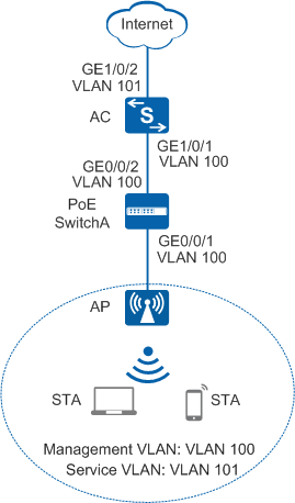
An enterprise has a small-scale branch network. The enterprise needs to deploy WLAN services for mobile office so that its employees can access the enterprise internal network anywhere and anytime.
As shown in Figure 1, the AC is connected to the AP through a PoE switch, and the PoE switch supplies power to the AP. The WLAN service is configured on the AC, and delivered to APs.
Data Planning
Item |
Data |
|---|---|
DHCP server |
The AC functions as a DHCP server to assign IP addresses to APs and STAs. |
IP address pool for APs |
10.23.100.2-10.23.100.254/24 |
IP address pool for STAs |
10.23.101.2-10.23.101.254/24 |
IP address of the AC's source interface |
VLANIF 100: 10.23.100.1/24 |
AP group |
|
Regulatory domain profile |
|
SSID profile |
|
Security profile |
|
VAP profile |
|
Configuration Roadmap
The configuration roadmap is as follows:
- Configure the AP, AC, SwitchA, and upstream device to implement Layer 2 interoperation.
- Configure the AC to function as a DHCP server to assign IP addresses to the STAs and AP.
- Configure the AP to go online.
- Create an AP group to allow for the unified configuration of multiple APs.
- Configure AC system parameters, including the country code and source interface used by the AC to communicate with the AP.
- Configure the AP authentication mode and import the AP offline so that the AP can go online properly.
- Configure WLAN service parameters for STAs to access the WLAN.
Procedure
- Set the NAC mode to unified mode on the AC (default setting). Configure SwitchA and the AC to allow the AP and AC to transmit CAPWAP packets.
# Add GE0/0/1 that connects SwitchA to the AP and GE0/0/2 that connects SwitchA to the AC to the management VLAN 100.
<HUAWEI> system-view
[HUAWEI] sysname SwitchA
[SwitchA] vlan batch 100
[SwitchA] interface gigabitethernet 0/0/1
[SwitchA-GigabitEthernet0/0/1] port link-type trunk
[SwitchA-GigabitEthernet0/0/1] port trunk pvid vlan 100
[SwitchA-GigabitEthernet0/0/1] port trunk allow-pass vlan 100
[SwitchA-GigabitEthernet0/0/1] undo port trunk allow-pass vlan 1
[SwitchA-GigabitEthernet0/0/1] stp edged-port enable
[SwitchA-GigabitEthernet0/0/1] port-isolate enable
[SwitchA-GigabitEthernet0/0/1] quit
[SwitchA] interface gigabitethernet 0/0/2
[SwitchA-GigabitEthernet0/0/2] port link-type trunk
[SwitchA-GigabitEthernet0/0/2] port trunk allow-pass vlan 100
[SwitchA-GigabitEthernet0/0/2] undo port trunk allow-pass vlan 1
[SwitchA-GigabitEthernet0/0/2] quit
# Add GE1/0/1 that connects the AC to SwitchA to VLAN 100.
<HUAWEI> system-view
[HUAWEI] sysname AC
[AC] vlan batch 100 101
[AC] interface gigabitethernet 1/0/1
[AC-GigabitEthernet1/0/1] port link-type trunk
[AC-GigabitEthernet1/0/1] port trunk allow-pass vlan 100
[AC-GigabitEthernet1/0/1] undo port trunk allow-pass vlan 1
[AC-GigabitEthernet1/0/1] quit
- Configure the AC to communicate with the upstream device.

Configure AC uplink interfaces to transparently transmit service VLAN packets as required and communicate with the upstream device.
# Add AC uplink interface GE1/0/2 to service VLAN 101.
[AC] interface gigabitethernet 1/0/2
[AC-GigabitEthernet1/0/2] port link-type trunk
[AC-GigabitEthernet1/0/2] port trunk allow-pass vlan 101
[AC-GigabitEthernet1/0/2] undo port trunk allow-pass vlan 1
[AC-GigabitEthernet1/0/2] quit
- Configure the AC as a DHCP server to allocate IP addresses to STAs and the AP.
# Configure the AC as the DHCP server to allocate an IP address to the AP from the IP address pool on VLANIF 100, and allocate IP addresses to STAs from the IP address pool on VLANIF 101.
Configure the DNS server as required. The common methods are as follows:- In interface address pool scenarios, run the dhcp server dns-list ip-address &<1-8> command in the VLANIF interface view.
- In global address pool scenarios, run the dns-list ip-address &<1-8> command in the IP address pool view.
[AC] dhcp enable  //Enable the DHCP function.
[AC] interface vlanif 100
[AC-Vlanif100] ip address 10.23.100.1 24
[AC-Vlanif100] dhcp select interface  //Configure an interface-based address pool.
[AC-Vlanif100] quit
[AC] interface vlanif 101
[AC-Vlanif101] ip address 10.23.101.1 24
[AC-Vlanif101] dhcp select interface
[AC-Vlanif101] quit
- Configure the AP to go online.
# Create an AP group.
[AC] wlan
[AC-wlan-view] ap-group name ap-group1
[AC-wlan-ap-group-ap-group1] quit
# Create a regulatory domain profile, configure the AC country code in the profile, and apply the profile to the AP group.
[AC-wlan-view] regulatory-domain-profile name domain1
[AC-wlan-regulate-domain-domain1] country-code cn
[AC-wlan-regulate-domain-domain1] quit
[AC-wlan-view] ap-group name ap-group1
[AC-wlan-ap-group-ap-group1] regulatory-domain-profile domain1
Warning: Modifying the country code will clear channel, power and antenna gain configurations of the radio and reset the AP. Continue?[Y/N]:y
[AC-wlan-ap-group-ap-group1] quit
[AC-wlan-view] quit
# Configure the AC's source interface.
[AC] capwap source interface vlanif 100
# Import an AP offline on the WLAN AC and add the AP to AP group ap-group1. Assume that the AP's MAC address is 60de-4476-e360. Configure a name for the AP based on the AP's deployment location, so that you can know where the AP is deployed from its name. For example, name the AP area_1 if it is deployed in Area 1. The default AP authentication mode is MAC address authentication. If the default settings are retained, you do not need to run the ap auth-mode mac-auth command.
The AP used in this example has two radios: radio 0 (2.4 GHz radio) and radio 1 (5 GHz radio).
[AC] wlan
[AC-wlan-view] ap auth-mode mac-auth
[AC-wlan-view] ap-id 0 ap-mac 60de-4476-e360
[AC-wlan-ap-0] ap-name area_1
[AC-wlan-ap-0] ap-group ap-group1
Warning: This operation may cause AP reset. If the country code changes, it will clear channel, power and antenna gain configuration s of the radio, Whether to continue? [Y/N]:y
[AC-wlan-ap-0] quit
# Power on the AP and run the display ap all command to check the AP state. If the State field is displayed as nor, the AP has gone online.
[AC-wlan-view] display ap all
Total AP information:
nor  : normal          [1]
Extrainfo : Extra information
P  : insufficient power supply
--------------------------------------------------------------------------------------------------
ID   MAC            Name   Group     IP            Type            State STA Uptime      ExtraInfo
--------------------------------------------------------------------------------------------------
0    60de-4476-e360 area_1 ap-group1 10.23.100.254 AP5030DN        nor   0   10S         -
--------------------------------------------------------------------------------------------------
Total: 1
- Configure WLAN service parameters.# Create security profile wlan-security and set the security policy in the profile.
In this example, the security policy is set to WPA2+PSK+AES and password to a1234567. In actual situations, the security policy must be configured according to service requirements.
[AC-wlan-view] security-profile name wlan-security
[AC-wlan-sec-prof-wlan-security] security wpa2 psk pass-phrase a1234567 aes  //Configure security policy WPA2+PSK+AES.
[AC-wlan-sec-prof-wlan-security] quit
# Create SSID profile wlan-ssid and set the SSID name to wlan-net.
[AC-wlan-view] ssid-profile name wlan-ssid
[AC-wlan-ssid-prof-wlan-ssid] ssid wlan-net  //Set the SSID to wlan-net.
[AC-wlan-ssid-prof-wlan-ssid] quit
# Create VAP profile wlan-vap, set the data forwarding mode and service VLAN, and apply the security profile and SSID profile to the VAP profile.
[AC-wlan-view] vap-profile name wlan-vap
[AC-wlan-vap-prof-wlan-vap] forward-mode tunnel  //Set the service forwarding mode to tunnel.
[AC-wlan-vap-prof-wlan-vap] service-vlan vlan-id 101  //Set the VLAN ID to 101. By default, the VLAN ID is 1.
[AC-wlan-vap-prof-wlan-vap] security-profile wlan-security
[AC-wlan-vap-prof-wlan-vap] ssid-profile wlan-ssid
[AC-wlan-vap-prof-wlan-vap] quit
# Bind VAP profile wlan-vap to the AP group and apply the profile to radio 0 and radio 1 of the AP.
[AC-wlan-view] ap-group name ap-group1
[AC-wlan-ap-group-ap-group1] vap-profile wlan-vap wlan 1 radio 0
[AC-wlan-ap-group-ap-group1] vap-profile wlan-vap wlan 1 radio 1
[AC-wlan-ap-group-ap-group1] quit
- Commit the configuration.
[AC-wlan-view] commit all
Warning: Committing configuration may cause service interruption, continue?[Y/N]:y
- Verify the configuration.
After the service configuration is complete, run the display vap ssid wlan-net command. In the command output, if Status is ON, the VAPs have been successfully created on AP radios.
[AC-wlan-view] display vap ssid wlan-net
WID : WLAN ID
--------------------------------------------------------------------------------
AP ID AP name RfID WID     BSSID          Status  Auth type     STA   SSID
--------------------------------------------------------------------------------
0     area_1  0    1       60DE-4476-E360 ON      WPA2-PSK      0     wlan-net
0     area_1  1    1       60DE-4476-E370 ON      WPA2-PSK      0     wlan-net
-------------------------------------------------------------------------------
Total: 2
Connect STAs to the WLAN with SSID wlan-net and enter the password a1234567. Run the display station ssid wlan-net command on the AC. The command output shows that the STAs are connected to the WLAN wlan-net.
[AC-wlan-view] display station ssid wlan-net
Rf/WLAN: Radio ID/WLAN ID
Rx/Tx: link receive rate/link transmit rate(Mbps)
---------------------------------------------------------------------------------
STA MAC         AP ID Ap name   Rf/WLAN  Band  Type  Rx/Tx      RSSI  VLAN  IP address
---------------------------------------------------------------------------------
e019-1dc7-1e08  0     area_1    1/1      5G    11n   46/59      -68   101   10.23.101.254
---------------------------------------------------------------------------------
Total: 1 2.4G: 0 5G: 1
Configuration Files
-
#
sysname SwitchA
#
vlan batch 100
#
interface GigabitEthernet0/0/1
 port link-type trunk
 port trunk pvid vlan 100
 undo port trunk allow-pass vlan 1
 port trunk allow-pass vlan 100
 stp edged-port enable
 port-isolate enable group 1
#
interface GigabitEthernet0/0/2
 port link-type trunk
 undo port trunk allow-pass vlan 1
 port trunk allow-pass vlan 100
#
return
AC configuration file
#
sysname AC
#
vlan batch 100 to 101
#
dhcp enable
#
interface Vlanif100
 ip address 10.23.100.1 255.255.255.0
 dhcp select interface
#
interface Vlanif101
 ip address 10.23.101.1 255.255.255.0
 dhcp select interface
#
interface GigabitEthernet1/0/1
 port link-type trunk
 undo port trunk allow-pass vlan 1
 port trunk allow-pass vlan 100
#
interface GigabitEthernet1/0/2
 port link-type trunk
 undo port trunk allow-pass vlan 1
 port trunk allow-pass vlan 101
#
capwap source interface vlanif100
#
wlan
 security-profile name wlan-security
  security wpa2 psk pass-phrase %^%#m"tz0f>~7.[`^6RWdzwCy16hJj/Mc!,}s`X*B]}A%^%# aes
 ssid-profile name wlan-ssid
  ssid wlan-net
 vap-profile name wlan-vap
  forward-mode tunnel
  service-vlan vlan-id 101
  ssid-profile wlan-ssid
  security-profile wlan-security
 regulatory-domain-profile name domain1
 ap-group name ap-group1
  regulatory-domain-profile domain1
  radio 0
   vap-profile wlan-vap wlan 1
  radio 1
   vap-profile wlan-vap wlan 1
 ap-id 0 type-id 35 ap-mac 60de-4476-e360 ap-sn 210235554710CB000042
  ap-name area_1
  ap-group ap-group1
#
return