Example for Configuring Unified Access for Wired and Wireless Users
Overview of Unified Access for Wired and Wireless Users
In practice, both wired and wireless users need to access one network. For example, the PCs and printers of a company connect to the network in wired mode, and laptops and mobile phones connect wirelessly. After unified access for wired and wireless users is configured on a network, users of both types can access the network and be managed in a unified manner.
Configuration Notes
- In this example, Portal authentication is used. To ensure network security, configure an appropriate security policy according to service requirements.
In tunnel forwarding mode, the management VLAN and service VLAN cannot be the same. If you set the forwarding mode to direct forwarding, you are not advised to configure the management VLAN and service VLAN to be the same.
In direct forwarding mode, configure port isolation on the interface directly connected to APs. If port isolation is not configured, many broadcast packets will be transmitted in the VLANs or WLAN users on different APs can directly communicate at Layer 2.
- Configure the management VLAN and service VLAN:
- In tunnel forwarding mode, service packets are encapsulated in a CAPWAP tunnel and forwarded to the AC. The AC then forwards the packets to the upper-layer network or APs. Service packets and management packets can be forwarded normally only if the network between the AC and APs is added to the management VLAN and the network between the AC and upper-layer network is added to the service VLAN.
- In direct forwarding mode, service packets are not encapsulated into a CAPWAP tunnel, but are directly forwarded to the upper-layer network or APs. Service packets and management packets can be forwarded normally only if the network between the AC and APs is added to the management VLAN and the network between APs and upper-layer network is added to the service VLAN.
- How to configure the source interface:
- In V200R006, run the wlan ac source interface { loopback loopback-number | vlanif vlan-id } command in the WLAN view.
- In V200R007 and V200R008, run the capwap source interface { loopback loopback-number | vlanif vlan-id } command in the system view.
- No ACK mechanism is provided for multicast packet transmission on air interfaces. In addition, wireless links are unstable. To ensure stable transmission of multicast packets, they are usually sent at low rates. If a large number of such multicast packets are sent from the network side, the air interfaces may be congested. You are advised to configure multicast packet suppression to reduce impact of a large number of low-rate multicast packets on the wireless network. Exercise caution when configuring the rate limit; otherwise, the multicast services may be affected.
- In direct forwarding mode, you are advised to configure multicast packet suppression on switch interfaces connected to APs.
- In tunnel forwarding mode, you are advised to configure multicast packet suppression in traffic profiles of the AC.
- The following table lists applicable products and versions.
Table 1 Applicable products and versions Software Version
Product Model
AP Model and Version
V200R005C00
S7700, S9700
V200R005C00:
AP2010DN, AP3010DN-AGN, AP5010DN-AGN, AP5010SN-GN, AP5030DN, AP5130DN, AP6010SN-GN, AP6010DN-AGN, AP6310SN-GN, AP6510DN-AGN, AP6610DN-AGN, AP7110DN-AGN, AP7110SN-GN
V200R006C00
S5720-HI, S7700, S9700
V200R005C00:
AP2010DN, AP3010DN-AGN, AP5010DN-AGN, AP5010SN-GN, AP5030DN, AP5130DN, AP6010SN-GN, AP6010DN-AGN, AP6310SN-GN, AP6510DN-AGN, AP6610DN-AGN, AP7110DN-AGN, AP7110SN-GN
V200R007C00
S5720-HI, S7700, S9700
V200R005C10:
AP2010DN, AP3010DN-AGN, AP5010DN-AGN, AP5010SN-GN, AP5030DN, AP5130DN, AP6010SN-GN, AP6010DN-AGN, AP6310SN-GN, AP6510DN-AGN, AP6610DN-AGN, AP7110DN-AGN, AP7110SN-GN, AP8030DN, AP8130DN
V200R005C20:
AP7030DE, AP9330DN
V200R008C00
S5720-HI, S7700, S9700
V200R005C10:
AP2010DN, AP3010DN-AGN, AP5010DN-AGN, AP5010SN-GN, AP5030DN, AP5130DN, AP6010SN-GN, AP6010DN-AGN, AP6310SN-GN, AP6510DN-AGN, AP6610DN-AGN, AP7110DN-AGN, AP7110SN-GN, AP8030DN, AP8130DN
V200R005C20:
AP7030DE, AP9330DN
V200R005C30:
AP2030DN, AP4030DN, AP4130DN

For S7700, you are advised to deploy S7712 or S7706 switches for WLAN services. S7703 switches are not recommended.
For S9700, you are advised to deploy S9712 or S9706 switches for WLAN services. S9703 switches are not recommended.
Networking Requirements
A hospital needs to deploy both a wired and a wireless network. To simplify management and maintenance, the administrator requires that wired and wireless users be centrally managed on the AC, non-authentication and Portal authentication be configured for the wired and wireless users respectively, and wireless users roam under the same AC.
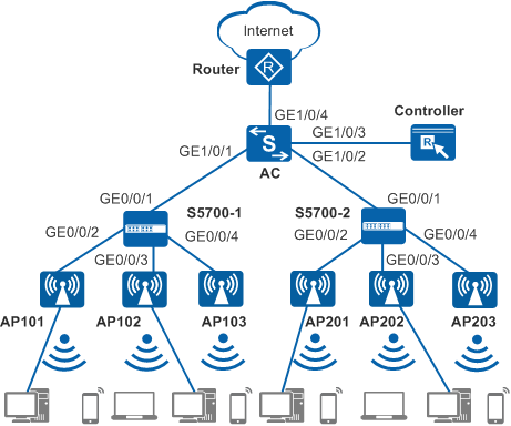
As shown in Figure 1, the AC connects to the egress gateway Router in the uplink direction. In the downlink direction, the AC connects to and manages APs through S5700-1 and S5700-2 access switches. The S5700-1 and S5700-2 are deployed in the first and second floors, respectively. An AP2010DN is deployed in each room to provide both wired and wireless access. The AP5030DN is deployed in the corridor to provide wireless network coverage. The S5700-1 and S5700-2 are PoE switches directly providing power to connected APs.
To facilitate network planning and management, the access switches are only used to transparently transmit data at Layer 2, and all gateways are configured on the AC
The AC functions as the DHCP server to allocate IP addresses to APs, STAs, and PCs.
Data Planning
Item |
Interface |
VLAN |
Description |
|---|---|---|---|
AC |
GE1/0/1 |
100, 201 |
Connected to the S5700-1 |
GE1/0/2 |
100, 202 |
Connected to the S5700-2 |
|
GE1/0/3 |
200 |
Connected to the controller |
|
GE1/0/4 |
300 |
Connected to the egress gateway |
|
S5700-1 |
GE0/0/1 |
100, 201 |
Connected to the AC |
GE0/0/2 |
100, 201 |
Connected to AP101 |
|
GE0/0/3 |
100, 201 |
Connected to AP102 |
|
GE0/0/4 |
100, 201 |
Connected to AP103 |
|
S5700-2 |
GE0/0/1 |
100, 202 |
Connected to the AC |
GE0/0/2 |
100, 202 |
Connected to AP201 |
|
GE0/0/3 |
100, 202 |
Connected to AP202 |
|
GE0/0/4 |
100, 202 |
Connected to AP203 |
|
AP101 and AP102 |
Eth0/0/0 Eth0/0/1 GE0/0/0 |
201 |
GE0/0/0 connects to the S5700-1. Eth0/0/0 and Eth0/0/1 connects to wired users. AP101 and AP102 are AP2010DNs and are deployed in rooms on the first floor to provide wired and wireless access. |
AP103 |
- |
- |
AP103 is an AP5030DN and is deployed in the corridor on the first floor to provide wireless access. |
AP201 and AP202 |
Eth0/0/0 Eth0/0/1 GE0/0/0 |
202 |
GE0/0/0 connects to the S5700-2. Eth0/0/0 and Eth0/0/1 connects to wired users. AP201 and AP202 are AP2010DNs and are deployed in rooms on the second floor to provide wired and wireless access. |
AP203 |
- |
- |
AP203 is an AP5030DN and is deployed in the corridor on the second floor to provide wireless access. |
Item |
Data |
Description |
|---|---|---|
IP address of the AC's source interface |
10.23.100.1/24 |
- |
Country code |
CN |
- |
WMM profile |
Name: wmm |
- |
Radio profile |
Name: radio |
- |
Security profile |
|
- |
Traffic profile |
Name: traffic |
- |
Service set |
|
Provides WLAN network coverage for the first floor. |
|
Provides WLAN network coverage for the second floor. |
|
DHCP server |
The AC functions as the DHCP server to allocate IP addresses to APs, STAs, and PCs. |
- |
AP gateway and IP address pool range |
VLANIF 100: 10.23.100.1/24 10.23.100.2-10.23.100.254/24 |
- |
Gateway and IP address pool range of the wireless users |
VLANIF 101: 10.23.101.1/24 10.23.101.2-10.23.101.254/24 |
- |
VLANIF 102: 10.23.102.1/24 10.23.102.2-10.23.102.254/24 |
- |
|
Gateway and IP address pool range of the wired users |
VLANIF 201: 10.23.201.1/24 10.23.201.2-10.23.201.254/24 |
- |
VLANIF 202: 10.23.202.1/24 10.23.202.2-10.23.202.254/24 |
- |
|
Server parameters |
Authentication server:
|
|
Accounting server:
|
||
Authorization server:
|
||
Portal server:
|
Item |
Data |
Description |
|---|---|---|
AP101 |
Radio 0: channel 1 and power level 10 |
Use the WLAN Planner to plan AP installation locations, and the working channel and power of the AP radio. Set the channel mode and power mode to fixed, and configure the channel and power for each AP. |
AP102 |
Radio 0: channel 6 and power level 10 |
|
AP103 |
Radio 0: channel 11 and power level 10 Radio 1: channel 153 and power level 10 |
|
AP201 |
Radio 0: channel 1 and power level 10 |
|
AP202 |
Radio 0: channel 6 and power level 10 |
|
AP203 |
Radio 0: channel 11 and power level 10 Radio 1: channel 157 and power level 10 |
Configuration Roadmap
The configuration roadmap is as follows:
- Configure all network devices to enable the APs, S5700-1, S5700-2, and AC to communicate with upper-layer devices.
- Configure the AC as a DHCP server to assign IP addresses to APs, wired users, and wireless users.
- Configure a RADIUS server template, configure authentication, accounting, and authorization in the template, and configure Portal authentication.
- Configure basic WLAN services, including AC system parameters, AP management, and WLAN service parameters.
- Configure VAPs and deliver VAP parameters to APs.
- Verify the configuration to ensure that both wired and wireless users can access the Internet.
Procedure
- Configure network devices to communicate with each other.
# Add GE0/0/1 to GE0/0/4 of the S5700-1 to VLAN 100 (management VLAN) and VLAN 201 (VLAN for wired service packets), and add GE0/0/1 to GE0/0/4 of the S5700-2 to VLAN 100 and VLAN 202 (VLAN for wireless service packets). Set PVIDs for interfaces directly connected to APs. You are advised to configure port isolation on these interfaces to reduce unnecessary broadcast traffic. The S5700-1 is used as an example here. The configuration on the S5700-2 is similar. For details, see the configuration file of the S5700-2.
[HUAWEI] sysname S5700-1
[S5700-1] vlan batch 100 201
[S5700-1] interface gigabitethernet 0/0/1
[S5700-1-GigabitEthernet0/0/1] port link-type trunk
[S5700-1-GigabitEthernet0/0/1] port trunk allow-pass vlan 100 201
[S5700-1-GigabitEthernet0/0/1] quit
[S5700-1] interface gigabitethernet 0/0/2
[S5700-1-GigabitEthernet0/0/2] port link-type trunk
[S5700-1-GigabitEthernet0/0/2] port trunk allow-pass vlan 100 201
[S5700-1-GigabitEthernet0/0/2] port trunk pvid vlan 100   //Set a PVID for the interface directly connected to the AP.
[S5700-1-GigabitEthernet0/0/2] port-isolate enable   //Configure port isolation to reduce broadcast packets.
[S5700-1-GigabitEthernet0/0/2] quit
[S5700-1] interface gigabitethernet 0/0/3
[S5700-1-GigabitEthernet0/0/3] port link-type trunk
[S5700-1-GigabitEthernet0/0/3] port trunk allow-pass vlan 100 201
[S5700-1-GigabitEthernet0/0/3] port trunk pvid vlan 100
[S5700-1-GigabitEthernet0/0/3] port-isolate enable
[S5700-1-GigabitEthernet0/0/3] quit
[S5700-1] interface gigabitethernet 0/0/4
[S5700-1-GigabitEthernet0/0/4] port link-type trunk
[S5700-1-GigabitEthernet0/0/4] port trunk allow-pass vlan 100 201
[S5700-1-GigabitEthernet0/0/4] port trunk pvid vlan 100
[S5700-1-GigabitEthernet0/0/4] port-isolate enable
[S5700-1-GigabitEthernet0/0/4] quit
# On the AC, add GE1/0/1 (connected to the S5700-1) to VLAN 100 and VLAN 201, GE1/0/2 (connected to the S5700-2) to VLAN 100 and VLAN 202, GE1/0/4 (connected to the upper-layer network) to VLAN 300, and GE1/0/3 (connected to the controller) to VLAN 200.
[HUAWEI] sysname AC
[AC] vlan batch 100 200 201 202 300
[AC] interface gigabitethernet 1/0/1
[AC-GigabitEthernet1/0/1] port link-type trunk
[AC-GigabitEthernet1/0/1] port trunk allow-pass vlan 100 201
[AC-GigabitEthernet1/0/1] quit
[AC] interface gigabitethernet 1/0/2
[AC-GigabitEthernet1/0/2] port link-type trunk
[AC-GigabitEthernet1/0/2] port trunk allow-pass vlan 100 202
[AC-GigabitEthernet1/0/2] quit
[AC] interface gigabitethernet 1/0/3
[AC-GigabitEthernet1/0/3] port link-type trunk
[AC-GigabitEthernet1/0/3] port trunk allow-pass vlan 200
[AC-GigabitEthernet1/0/3] quit
[AC] interface gigabitethernet 1/0/4
[AC-GigabitEthernet1/0/4] port link-type trunk
[AC-GigabitEthernet1/0/4] port trunk allow-pass vlan 300
[AC-GigabitEthernet1/0/4] quit
# Configure VLANIF 200 for communication between the AC and controller.
[AC] interface vlanif200 [AC-Vlanif200] ip address 10.23.200.2 24 //Configure an IP address for communication between the AC and controller. [AC-Vlanif200] quit - Configure the AC as a DHCP server to assign IP addresses to PCs, APs, and STAs. Configure the DNS server as required. The common methods are as follows:
- In interface address pool scenarios, run the dhcp server dns-list ip-address &<1-8> command in the VLANIF interface view.
- In global address pool scenarios, run the dns-list ip-address &<1-8> command in the IP address pool view.
# Configure the AC to assign IP addresses to PCs, APs, and STAs from an interface address pool.
[AC] dhcp enable
[AC] vlan batch 101 102
[AC] interface vlanif 100  //Configure an interface address pool to assign IP addresses to APs.
[AC-Vlanif100] description manage_ap
[AC-Vlanif100] ip address 10.23.100.1 24
[AC-Vlanif100] dhcp select interface
[AC-Vlanif100] quit
[AC] interface vlanif 101  //Configure an interface address pool to assign IP addresses to STAs on the first floor.
[AC-Vlanif101] description manage_floor1_sta
[AC-Vlanif101] ip address 10.23.101.1 24
[AC-Vlanif101] dhcp select interface
[AC-Vlanif101] quit
[AC] interface vlanif 102  //Configure an interface address pool to assign IP addresses to STAs on the second floor.
[AC-Vlanif102] description manage_floor2_sta
[AC-Vlanif102] ip address 10.23.102.1 24
[AC-Vlanif102] dhcp select interface
[AC-Vlanif102] quit
[AC] interface vlanif 201  //Configure an interface address pool to assign IP addresses to PCs on the first floor.
[AC-Vlanif201] description manage_floor1_pc
[AC-Vlanif201] ip address 10.23.201.1 24
[AC-Vlanif201] dhcp select interface
[AC-Vlanif201] quit
[AC] interface vlanif 202  //Configure an interface address pool to assign IP addresses to PCs on the second floor.
[AC-Vlanif202] description manage_floor2_pc
[AC-Vlanif202] ip address 10.23.202.1 24
[AC-Vlanif202] dhcp select interface
[AC-Vlanif202] quit
- Configure a RADIUS server template, configure authentication, accounting, and authorization in the template, and configure Portal authentication.
# Configure a RADIUS server template on the AC, and configure authentication, accounting, and authorization in the template.
[AC] radius-server template radius1  //Create the RADIUS server template radius1
[AC-radius-radius1] radius-server authentication 10.23.200.1 1812 source ip-address 10.23.200.2 weight 80   //Configure the RADIUS authentication server and authentication port 1812. The AC uses the IP address 10.23.200.2 to communicate with the RADIUS server.
[AC-radius-radius1] radius-server accounting 10.23.200.1 1813 source ip-address 10.23.200.2 weight 80   //Configure the RADIUS accounting server to collect user login and logout information and set the accounting port number to 1813. The AC uses the IP address 10.23.200.2 to communicate with the RADIUS server
[AC-radius-radius1] radius-server shared-key cipher Admin@123   //Configure the shared key for the RADIUS server.
[AC-radius-radius1] undo radius-server user-name domain-included   //The user name that the device sends to the RADIUS server does not carry the domain name. Configure the command when the RADIUS server does not accept the user name with the domain name.
[AC-radius-radius1] quit
[AC] radius-server authorization 10.23.200.1 shared-key cipher Admin@123   //Configure an IP address for the RADIUS authorization server, set the shared key to Admin@123, same as the authentication and accounting keys. Configure the authorization server so that the RADIUS server can deliver authorization rules to the AC.
[AC] aaa
[AC-aaa] authentication-scheme radius1  //Create the authentication scheme radius1.
[AC-aaa-authen-radius1] authentication-mode radius   //If the controller functions as the RADIUS server, the authentication mode must be set to RADIUS.
[AC-aaa-authen-radius1] quit
[AC-aaa] accounting-scheme radius1  //Create the accounting scheme radius 1.
[AC-aaa-accounting-radius1] accounting-mode radius   //Set the accounting mode to RADIUS. To facilitate account status information maintenance on the RADIUS server, including the login and logout information, and forced logout information, the accounting mode must be set to radius.
[AC-aaa-accounting-radius1] quit
[AC-aaa] domain portal1   //Create the domain portal1.
[AC-aaa-domain-portal1] authentication-scheme radius1  //Bind the authentication scheme radius1.
[AC-aaa-domain-portal1] accounting-scheme radius1  //Bind the accounting scheme radius1.
[AC-aaa-domain-portal1] radius-server radius1  //Bind the RADIUS server template radius1.
[AC-aaa-domain-portal1] quit
[AC-aaa] quit
# Configure the Portal server.
[AC] web-auth-server portal1  //Create the Portal server template portal1.
[AC-web-auth-server-portal1] server-ip 10.23.200.1  //Configure an IP address for the Portal server.
[AC-web-auth-server-portal1] port 50200  //Set the destination port number used by the device to send packets to the Portal server to 50200 (default setting).
[AC-web-auth-server-portal1] shared-key cipher Admin@123  //Configure the shared key for message exchange between the AC and Portal server.
[AC-web-auth-server-portal1] url http://10.23.200.1:8080/portal  //Configure the URL for a Portal server.
[AC-web-auth-server-portal1] quit
# Bind the Portal server template to the WLAN-ESS interface, enable Portal authentication for wireless users, and configure non-authentication for wired users.
[AC] interface wlan-ess 1
[AC-Wlan-Ess1] domain name portal1 force  //Configure the forcible user domain portal1.
[AC-Wlan-Ess1] domain name portal1  //Configure the default user domain portal1.
[AC-Wlan-Ess1] authentication portal  //Configure Portal authentication.
[AC-Wlan-Ess1] web-auth-server portal1 direct  //Bind the Portal server template portal1 and specify Layer 2 authentication as the Portal authentication mode.
[AC-Wlan-Ess1] quit
[AC] interface wlan-ess 2
[AC-Wlan-Ess2] domain name portal1 force  //Configure the forcible user domain portal1.
[AC-Wlan-Ess2] domain name portal1  //Configure the default user domain portal1.
[AC-Wlan-Ess2] authentication portal  //Configure Portal authentication.
[AC-Wlan-Ess2] web-auth-server portal1 direct  //Bind the Portal server template portal1 and specify Layer 2 authentication as the Portal authentication mode.
[AC-Wlan-Ess2] quit
- Configure AC system parameters.
# Configure the AC's country code.
[AC] wlan ac-global country-code cn  //Configure the AC country code. Radio features of APs managed by the AC must conform to local laws and regulations. The default country code is CN.
Warning: Modifying the country code will clear channel configurations of the AP radio using the country code and reset the AP. If th
e new country code does not support the radio, all configurations of the radio are cleared. Continue?[Y/N]:y
# Configure the AC ID and carrier ID.
[AC] wlan ac-global ac id 1 carrier id other //The default AC ID is 0. Set the AC ID to 1.# Configure the AC's source interface.
[AC] capwap source interface vlanif 100
[AC] wlan
- Manage the APs on the AC.
# Check the AP type IDs after obtaining the MAC addresses of the APs.
[AC-wlan-view] display ap-type all
  All AP types information:
  ------------------------------------------------------------------------------
  ID     Type
  ------------------------------------------------------------------------------
  17     AP6010SN-GN
  19     AP6010DN-AGN
  21     AP6310SN-GN
  23     AP6510DN-AGN
  25     AP6610DN-AGN
  27     AP7110SN-GN
  28     AP7110DN-AGN
  29     AP5010SN-GN
  30     AP5010DN-AGN
  31     AP3010DN-AGN
  33     AP6510DN-AGN-US
  34     AP6610DN-AGN-US
  35     AP5030DN
  36     AP5130DN
  37     AP7030DE
  38     AP2010DN
  39     AP8130DN
  40     AP8030DN
  42     AP9330DN
  43     AP4030DN
  44     AP4130DN
  45     AP3030DN
  46     AP2030DN
  ------------------------------------------------------------------------------
  Total number: 23
# Set the AP authentication mode to MAC address authentication (default setting). Add the APs offline based on the obtained AP type IDs.
[AC-wlan-view] ap id 101 type-id 38 mac 60de-4476-e320  //Add the AP2010DN offline with the MAC address 60de-4476-e320 and AP ID 101.
[AC-wlan-ap-101] quit
[AC-wlan-view] ap id 102 type-id 38 mac 60de-4476-e340  //Add the AP2010DN offline with the MAC address 60de-4476-e340 and AP ID 102.
[AC-wlan-ap-102] quit
[AC-wlan-view] ap id 103 type-id 35 mac dcd2-fc04-b520  //Add the AP5030DN offline with the MAC address dcd2-fc04-b520 and AP ID 103.
[AC-wlan-ap-103] quit
[AC-wlan-view] ap id 201 type-id 38 mac 60de-4476-e360  //Add the AP2010DN offline with the MAC address 60de-4476-e360 and AP ID 201.
[AC-wlan-ap-201] quit
[AC-wlan-view] ap id 202 type-id 38 mac 60de-4476-e380  //Add the AP2010DN offline with the MAC address 60de-4476-e380 and AP ID 202.
[AC-wlan-ap-202] quit
[AC-wlan-view] ap id 203 type-id 35 mac dcd2-fc04-b540  //Add the AP5030DN offline with the MAC address dcd2-fc04-b540 and AP ID 203.
[AC-wlan-ap-203] quit
# Configure AP regions and add the APs to the AP regions.
[AC-wlan-view] ap-region id 1  //Create AP region1 and add APs on the first floor to AP region1.
[AC-wlan-ap-region-1] ap-region-name floor1  //Name the AP region1 floor1.
[AC-wlan-ap-region-1] quit
[AC-wlan-view] ap id 101
[AC-wlan-ap-101] region-id 1  //Add AP 101 to AP region1.
[AC-wlan-ap-101] quit
[AC-wlan-view] ap id 102
[AC-wlan-ap-102] region-id 1
[AC-wlan-ap-102] quit
[AC-wlan-view] ap id 103
[AC-wlan-ap-103] region-id 1
[AC-wlan-ap-103] quit
[AC-wlan-view] ap-region id 2  //Create AP region2 and add APs on the second floor to AP region2.
[AC-wlan-ap-region-2] ap-region-name floor2
[AC-wlan-ap-region-2] quit
[AC-wlan-view] ap id 201
[AC-wlan-ap-201] region-id 2
[AC-wlan-ap-201] quit
[AC-wlan-view] ap id 202
[AC-wlan-ap-202] region-id 2
[AC-wlan-ap-202] quit
[AC-wlan-view] ap id 203
[AC-wlan-ap-203] region-id 2
[AC-wlan-ap-203] quit
# Power on the APs and run the display ap all command to check the AP state. If the AP State field is normal, the APs have gone online.
[AC-wlan-view] display ap all
  All AP(s) information:
  Normal[6],Fault[0],Commit-failed[0],Committing[0],Config[0],Download[0]
  Config-failed[0],Standby[0],Type-not-match[0],Ver-mismatch[0]
  ------------------------------------------------------------------------------
  AP    AP               AP              Profile   AP              AP
                                         /Region
  ID    Type             MAC             ID        State           Sysname
  ------------------------------------------------------------------------------
  101   AP2010DN         60de-4476-e320    0/1     normal          ap-101
  102   AP2010DN         60de-4476-e340    0/1     normal          ap-102
  103   AP5030DN         dcd2-fc04-b520    0/1     normal          ap-103
  201   AP2010DN         60de-4476-e360    0/2     normal          ap-201
  202   AP2010DN         60de-4476-e380    0/2     normal          ap-202
  203   AP5030DN         dcd2-fc04-b540    0/2     normal          ap-203
  ------------------------------------------------------------------------------
  Total number: 6,printed: 6
# Configure an AP2010DN's uplink interface GE0/0/0 and downlink interfaces Eth0/0/0 and Eth0/0/1 to allow wired service packets to pass.
[AC-wlan-view] ap id 101
[AC-wlan-ap-101] lineate-port ethernet 0 pvid vlan 201  //The downlink interface of the AP2010DN is used to connect wired terminals, such as the PCs. Set a PVID for the interface. VLAN 201 is used to transmit wired service packets of the first floor.
[AC-wlan-ap-101] lineate-port ethernet 0 vlan untagged 201  //The downlink interface of the AP2010DN is used to connect wired terminals. Add the interface to VLAN 201 in untagged mode.
[AC-wlan-ap-101] lineate-port ethernet 1 pvid vlan 201
[AC-wlan-ap-101] lineate-port ethernet 1 vlan untagged 201
[AC-wlan-ap-101] lineate-port gigabitethernet 0 vlan tagged 201  //The uplink interface of the AP2010DN is used to connect to the upper-layer devices. Add the interface to VLAN 201 in tagged mode.
[AC-wlan-ap-101] quit
[AC-wlan-view] ap id 102
[AC-wlan-ap-102] lineate-port ethernet 0 pvid vlan 201
[AC-wlan-ap-102] lineate-port ethernet 0 vlan untagged 201
[AC-wlan-ap-102] lineate-port ethernet 1 pvid vlan 201
[AC-wlan-ap-102] lineate-port ethernet 1 vlan untagged 201
[AC-wlan-ap-102] lineate-port gigabitethernet 0 vlan tagged 201
[AC-wlan-ap-102] quit
[AC-wlan-view] ap id 201
[AC-wlan-ap-201] lineate-port ethernet 0 pvid vlan 202  //The downlink interface of the AP2010DN is used to connect wired terminals, such as the PCs. Set a PVID for the interface. VLAN 202 is used to transmit wired service packets of the second floor.
[AC-wlan-ap-201] lineate-port ethernet 0 vlan untagged 202
[AC-wlan-ap-201] lineate-port ethernet 1 pvid vlan 202
[AC-wlan-ap-201] lineate-port ethernet 1 vlan untagged 202
[AC-wlan-ap-201] lineate-port gigabitethernet 0 vlan tagged 202
[AC-wlan-ap-201] quit
[AC-wlan-view] ap id 202
[AC-wlan-ap-202] lineate-port ethernet 0 pvid vlan 202
[AC-wlan-ap-202] lineate-port ethernet 0 vlan untagged 202
[AC-wlan-ap-202] lineate-port ethernet 1 pvid vlan 202
[AC-wlan-ap-202] lineate-port ethernet 1 vlan untagged 202
[AC-wlan-ap-202] lineate-port gigabitethernet 0 vlan tagged 202
[AC-wlan-ap-202] quit
- Configure WLAN service parameters.
# Create the WMM profile wmm.
[AC-wlan-view] wmm-profile name wmm id 1
[AC-wlan-wmm-prof-wmm] quit
# Create the radio profile radio and bind the WMM profile wmm to the radio profile.
[AC-wlan-view] radio-profile name radio id 1
[AC-wlan-radio-prof-radio] wmm-profile name wmm
[AC-wlan-radio-prof-radio] power-mode fixed  //Set the power mode of the radio to fixed.
[AC-wlan-radio-prof-radio] channel-mode fixed  //Set the channel mode of the radio to fixed.
[AC-wlan-radio-prof-radio] quit
[AC-wlan-view] quit
# Create WLAN-ESS interface 1 and WLAN-ESS interface 2.
[AC] interface wlan-ess 1
[AC-Wlan-Ess1] port trunk allow-pass vlan 101 102  //Configure the wlan-ess interface to allow packets from wireless service VLANs to pass through, which is one of the prerequisites for intra-AC roaming.
[AC-Wlan-Ess1] quit
[AC] interface wlan-ess 2
[AC-Wlan-Ess2] port trunk allow-pass vlan 101 102
[AC-Wlan-Ess2] quit
# Create the security profile security.
[AC] wlan
[AC-wlan-view] security-profile name security id 1  //Portal authentication has been enabled on the interface. Set the security policy to OPEN (default setting), that is, no authentication and no encryption.
[AC-wlan-sec-prof-security] quit
# Create the traffic profile traffic.
[AC-wlan-view] traffic-profile name traffic id 1
[AC-wlan-traffic-prof-traffic] quit
# Create service sets floor1 and floor2, and bind the service VLANs, WLAN-ESS interfaces, security profile, and traffic profile to the service sets. Set the forwarding mode to tunnel forwarding.
[AC-wlan-view] service-set name floor1 id 1  //Create the service set floor1.
[AC-wlan-service-set-floor1] ssid hospital-wlan  //Set the SSID to hospital-wlan.
[AC-wlan-service-set-floor1] wlan-ess 1  //Bind the WLAN-ESS interface.
[AC-wlan-service-set-floor1] security-profile name security  //Bind the security profile security.
[AC-wlan-service-set-floor1] traffic-profile name traffic  //Bind the traffic profile traffic.
[AC-wlan-service-set-floor1] service-vlan 101  //Bind the service VLAN 101.
[AC-wlan-service-set-floor1] forward-mode tunnel  //Set the forwarding mode to tunnel forwarding. The default forwarding mode is direct forwarding.
[AC-wlan-service-set-floor1] user-isolate  //Configure Layer 2 isolation for users connected to the same VAP.
[AC-wlan-service-set-floor1] quit
[AC-wlan-view] service-set name floor2 id 2
[AC-wlan-service-set-floor2] ssid hospital-wlan  //Set the SSID to hospital-wlan. All service sets must be configured with the same SSID, which is one of the prerequisites for intra-AC roaming.
[AC-wlan-service-set-floor2] wlan-ess 2
[AC-wlan-service-set-floor2] security-profile name security  //Bind the security profile security. All service sets must have the same security profile bound, which is one of the prerequisites for intra-AC roaming.
[AC-wlan-service-set-floor2] traffic-profile name traffic
[AC-wlan-service-set-floor2] service-vlan 102
[AC-wlan-service-set-floor2] forward-mode tunnel
[AC-wlan-service-set-floor2] user-isolate
[AC-wlan-service-set-floor2] quit
- Configure VAPs and deliver VAP parameters to the APs.
# Configure VAPs.
[AC-wlan-view] ap 101 radio 0  //Configure radio0 of the AP2010DN.
[AC-wlan-radio-101/0] radio-profile name radio  //Bind the radio profile to the radio.
[AC-wlan-radio-101/0] service-set name floor1  //Bind the service set to the radio. A VAP is generated after the binding.
[AC-wlan-radio-101/0] channel 20mhz 1  //Configure the channel based on the planning result of the WLAN Planner.
[AC-wlan-radio-101/0] power-level 10  //Configure the power based on the planning result of the WLAN Planner.
[AC-wlan-radio-101/0] quit
[AC-wlan-view] ap 102 radio 0
[AC-wlan-radio-102/0] radio-profile name radio
[AC-wlan-radio-102/0] service-set name floor1
[AC-wlan-radio-102/0] channel 20mhz 6
[AC-wlan-radio-102/0] power-level 10
[AC-wlan-radio-102/0] quit
[AC-wlan-view] ap 103 radio 0
[AC-wlan-radio-103/0] radio-profile name radio
[AC-wlan-radio-103/0] service-set name floor1
[AC-wlan-radio-103/0] channel 20mhz 11
[AC-wlan-radio-103/0] power-level 10
[AC-wlan-radio-103/0] quit
[AC-wlan-view] ap 103 radio 1  //The AP5030 supports two radios. This step configures radio 1.
[AC-wlan-radio-103/1] radio-profile name radio
[AC-wlan-radio-103/1] service-set name floor1
[AC-wlan-radio-103/1] channel 20mhz 153
[AC-wlan-radio-103/1] power-level 10
[AC-wlan-radio-103/1] quit
[AC-wlan-view] ap 201 radio 0
[AC-wlan-radio-201/0] radio-profile name radio
[AC-wlan-radio-201/0] service-set name floor2
[AC-wlan-radio-201/0] channel 20mhz 1
[AC-wlan-radio-201/0] power-level 10
[AC-wlan-radio-201/0] quit
[AC-wlan-view] ap 202 radio 0
[AC-wlan-radio-202/0] radio-profile name radio
[AC-wlan-radio-202/0] service-set name floor2
[AC-wlan-radio-202/0] channel 20mhz 6
[AC-wlan-radio-202/0] power-level 10
[AC-wlan-radio-202/0] quit
[AC-wlan-view] ap 203 radio 0
[AC-wlan-radio-203/0] radio-profile name radio
[AC-wlan-radio-203/0] service-set name floor2
[AC-wlan-radio-203/0] channel 20mhz 11
[AC-wlan-radio-203/0] power-level 10
[AC-wlan-radio-203/0] quit
[AC-wlan-view] ap 203 radio 1
[AC-wlan-radio-203/1] radio-profile name radio
[AC-wlan-radio-203/1] service-set name floor2
[AC-wlan-radio-203/1] channel 20mhz 157
[AC-wlan-radio-203/1] power-level 10
[AC-wlan-radio-203/1] quit
# Deliver the configuration to the APs.
[AC-wlan-view] commit all //After the WLAN service configuration is complete on the AC, the configuration takes effect after you deliver it to the APs. Warning: Committing configuration may cause service interruption, continue?[Y/N] :y - Verify the configuration.
# After the configuration is complete, run the display vap all command. The command output shows that VAPs have been created.
[AC-wlan-view] display vap all
  All VAP Information(Total-8):
  SS: Service-set     BP: Bridge-profile     MP: Mesh-profile
  ----------------------------------------------------------------------
  AP ID  Radio ID  SS ID  BP ID  MP ID  WLAN ID  BSSID           Type
  ----------------------------------------------------------------------
  101    0         1      -      -      1        60de-4476-e320  service
  102    0         1      -      -      1        60de-4476-e340  service
  103    0         1      -      -      1        dcd2-fc04-b520  service
  103    1         1      -      -      1        dcd2-fc04-b530  service
  201    0         2      -      -      1        60de-4476-e360  service
  202    0         2      -      -      1        60de-4476-e380  service
  203    0         2      -      -      1        dcd2-fc04-b540  service
  203    1         2      -      -      1        dcd2-fc04-b550  service
  ----------------------------------------------------------------------
  Total: 8
# STAs discover the WLAN with the SSID hospital-wlan and associate with the WLAN. The STAs are allocated IP addresses. After you enter the key, the STAs can access the wireless network. Run the display station assoc-info command on the AC. The command output shows that the STAs are connected to the WLAN hospital-wlan.
[AC-wlan-view] display station assoc-info all
  AP/Rf/WLAN: AP ID/Radio ID/WLAN ID
  Rx/Tx: link receive rate/link transmit rate(Mbps)
  ------------------------------------------------------------------------------
  STA MAC         AP/Rf/WLAN Rx/Tx     Mode  RSSI   IP address
  SSID
  ------------------------------------------------------------------------------
  e019-1dc7-1e08  101/0/1    6/11      11n   -89    10.23.101.254
  hospital-wlan
  ------------------------------------------------------------------------------
  Total stations: 1
# STAs and PCs obtain IP addresses and connect to the network properly.
Configuration Files
S5700-1 configuration file
#
sysname S5700-1
#
vlan batch 100 201
#
interface GigabitEthernet0/0/1
 port link-type trunk
 port trunk allow-pass vlan 100 201
#
interface GigabitEthernet0/0/2
 port link-type trunk
 port trunk pvid vlan 100
 port trunk allow-pass vlan 100 201
 port-isolate enable group 1
#
interface GigabitEthernet0/0/3
 port link-type trunk
 port trunk pvid vlan 100
 port trunk allow-pass vlan 100 201
 port-isolate enable group 1
#
interface GigabitEthernet0/0/4
 port link-type trunk
 port trunk pvid vlan 100
 port trunk allow-pass vlan 100 201
 port-isolate enable group 1
#
return
S5700-2 configuration file
#
sysname S5700-2
#
vlan batch 100 202
#
interface GigabitEthernet0/0/1
 port link-type trunk
 port trunk allow-pass vlan 100 202
#
interface GigabitEthernet0/0/2
 port link-type trunk
 port trunk pvid vlan 100
 port trunk allow-pass vlan 100 202
 port-isolate enable group 1
#
interface GigabitEthernet0/0/3
 port link-type trunk
 port trunk pvid vlan 100
 port trunk allow-pass vlan 100 202
 port-isolate enable group 1
#
interface GigabitEthernet0/0/4
 port link-type trunk
 port trunk pvid vlan 100
 port trunk allow-pass vlan 100 202
 port-isolate enable group 1
#
return
AC configuration file
#
sysname AC
#
vlan batch 100 to 102 200 to 202 300
#
wlan ac-global carrier id other ac id 1
#
dhcp enable
#
radius-server template radius1
 radius-server shared-key cipher %#%#ut)92(w\&0@UJ}J7}^3Z9x`9~Y$`2D1AGwDQ[+S.%#%#
 radius-server authentication 10.23.200.1 1812 source ip-address 10.23.200.2 weight 80
 radius-server accounting 10.23.200.1 1813 source ip-address 10.23.200.2 weight 80
 undo radius-server user-name domain-included
radius-server authorization 10.23.200.1 shared-key cipher %#%#[m1~SG]5CAzg~K35!b^Wa';{=+k_40Q\YK~}UX6T%#%#
#
web-auth-server portal1
 server-ip 10.23.200.1
 port 50200
 shared-key cipher %#%#^B],0yW|oJ1;j:U&`%}(=@2t*]e.$TOVrx@(I6rT%#%#
 url http://10.23.200.1:8080/portal
#
aaa
 authentication-scheme radius1
  authentication-mode radius
 accounting-scheme radius1
  accounting-mode radius
 domain portal1
  authentication-scheme radius1
  accounting-scheme radius1
  radius-server radius1
#
interface Vlanif100
 description manage_ap
 ip address 10.23.100.1 255.255.255.0
 dhcp select interface
#
interface Vlanif101
 description manage_floor1_sta
 ip address 10.23.101.1 255.255.255.0
 dhcp select interface
#
interface Vlanif102
 description manage_floor2_sta
 ip address 10.23.102.1 255.255.255.0
 dhcp select interface
#
interface Vlanif200
 ip address 10.23.200.2 255.255.255.0
#
interface Vlanif201
 description manage_floor1_pc
 ip address 10.23.201.1 255.255.255.0
 dhcp select interface
#
interface Vlanif202
 description manage_floor2_pc
 ip address 10.23.202.1 255.255.255.0
 dhcp select interface
#
interface GigabitEthernet1/0/1
 port link-type trunk
 port trunk allow-pass vlan 100 201
 #
interface GigabitEthernet1/0/2
 port link-type trunk
 port trunk allow-pass vlan 100 202
 #
interface GigabitEthernet1/0/3
 port link-type trunk
 port trunk allow-pass vlan 200
 #
interface GigabitEthernet1/0/4
 port link-type trunk
 port trunk allow-pass vlan 300
#
interface Wlan-Ess1
 port trunk allow-pass vlan 101 to 102
 domain name portal1 force
 domain name portal1
 authentication portal
 web-auth-server portal1 direct
#
interface Wlan-Ess2
 port trunk allow-pass vlan 101 to 102
 domain name portal1 force
 domain name portal1
 authentication portal
 web-auth-server portal1 direct
#
capwap source interface vlanif100
#
wlan
 ap-region id 1
  ap-region-name floor1
 ap-region id 2
  ap-region-name floor2
 ap id 101 type-id 38 mac 60de-4476-e320
  region-id 1
  lineate-port ethernet 0 pvid vlan 201
  lineate-port ethernet 0 vlan untagged 201
  lineate-port ethernet 1 pvid vlan 201
  lineate-port ethernet 1 vlan untagged 201
  lineate-port gigabitethernet 0 vlan tagged 201
 ap id 102 type-id 38 mac 60de-4476-e340
  region-id 1
  lineate-port ethernet 0 pvid vlan 201
  lineate-port ethernet 0 vlan untagged 201
  lineate-port ethernet 1 pvid vlan 201
  lineate-port ethernet 1 vlan untagged 201
  lineate-port gigabitethernet 0 vlan tagged 201
 ap id 103 type-id 35 mac dcd2-fc04-b520
  region-id 1
 ap id 201 type-id 38 mac 60de-4476-e360
  region-id 2
  lineate-port ethernet 0 pvid vlan 202
  lineate-port ethernet 0 vlan untagged 202
  lineate-port ethernet 1 pvid vlan 202
  lineate-port ethernet 1 vlan untagged 202
  lineate-port gigabitethernet 0 vlan tagged 202
 ap id 202 type-id 38 mac 60de-4476-e380
  region-id 2
  lineate-port ethernet 0 pvid vlan 202
  lineate-port ethernet 0 vlan untagged 202
  lineate-port ethernet 1 pvid vlan 202
  lineate-port ethernet 1 vlan untagged 202
  lineate-port gigabitethernet 0 vlan tagged 202
 ap id 203 type-id 35 mac dcd2-fc04-b540
  region-id 2
 wmm-profile name wmm id 1
 traffic-profile name traffic id 1
 security-profile name security id 1
 service-set name floor1 id 1
  forward-mode tunnel
  wlan-ess 1
  ssid hospital-wlan
  user-isolate
  traffic-profile id 1
  security-profile id 1
  service-vlan 101
 service-set name floor2 id 2
  forward-mode tunnel
  wlan-ess 2
  ssid hospital-wlan
  user-isolate
  traffic-profile id 1
  security-profile id 1
  service-vlan 102
 radio-profile name radio id 1
  channel-mode fixed
  power-mode fixed
  wmm-profile id 1
 ap 101 radio 0
  radio-profile id 1
  power-level 10
  service-set id 1 wlan 1
 ap 102 radio 0
  radio-profile id 1
  channel 20MHz 6
  power-level 10
  service-set id 1 wlan 1
 ap 103 radio 0
  radio-profile id 1
  channel 20MHz 11
  power-level 10
  service-set id 1 wlan 1
 ap 103 radio 1
  radio-profile id 1
  channel 20MHz 153
  power-level 10
  service-set id 1 wlan 1
 ap 201 radio 0
  radio-profile id 1
  power-level 10
  service-set id 2 wlan 1
 ap 202 radio 0
  radio-profile id 1
  channel 20MHz 6
  power-level 10
  service-set id 2 wlan 1
 ap 203 radio 0
  radio-profile id 1
  channel 20MHz 11
  power-level 10
  service-set id 2 wlan 1
 ap 203 radio 1
  radio-profile id 1
  channel 20MHz 157
  power-level 10
  service-set id 2 wlan 1
#
return