Network Design Suggestion
Enabling STP Edge Ports Connected to APs
To improve network stability and prevent network loops caused by incorrect connections, the Spanning Tree Protocol (STP) is enabled on the device by default. When an STP-enabled port on the device is connected to another device that does not support STP, the port is blocked for 30 seconds. It is recommended that switch ports connected to APs be configured as STP edge ports, so that the APs can rapidly connect to the network.
<HUAWEI> system-view
[HUAWEI] interface gigabitethernet 0/0/1
[HUAWEI-GigabitEthernet0/0/1] stp edged-port enable
Enabling LLDP on the PoE Ports Connected to APs
After the Link Layer Discovery Protocol (LLDP) is configured, the device can analyze powered devices (PDs). When LLDP is disabled, the device can detect and classify PDs only by analyzing the current and resistance between the device and PDs. Compared with current and resistance analysis, the LLDP function provides more comprehensive and accurate analysis.
Enable LLDP globally. After LLDP is enabled globally, the LLDP function is enabled on all ports by default.
<HUAWEI> system-view
[HUAWEI] lldp enable
Configuring VLANs
In practice, the management VLAN and service VLAN must be configured for management packets and service data packets.
- Management VLAN: transmits packets that are forwarded through CAPWAP tunnels, including management packets and service data packets forwarded through CAPWAP tunnels.
- Service VLAN: transmits service data packets.

It is recommended that you use different VLANs for the management VLAN and service VLAN.
You are not advised to use VLAN 1 as the management VLAN or service VLAN.
In tunnel forwarding mode, the management VLAN and service VLAN must be different. The network between the AC and AP can only permit packets with management VLAN tags to pass through, and cannot permit packets with service VLAN tags to pass through.
When a downlink GE interface of an AD9431DN-24X works in middle mode, the interface allows packets from all VLANs but no VLAN is created by default. VLANs are automatically created or deleted based on the VLAN list on the connected RU.
- When an AP connects to an AC through a Layer 2 network, VLAN m is the same as VLAN m', and VLAN s is the same as VLAN s'.
- When an AP connects to an AC through a Layer 3 network, VLAN m is different from VLAN m', and VLAN s is different from VLAN s'.
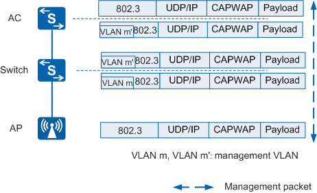
Figure 1 shows the process of forwarding management packets through CAPWAP tunnels.
In Figure 1:
- In the uplink direction (from the AP to the AC): When receiving management packets, the AP encapsulates the packets in CAPWAP packets. The switch tags the packets with VLAN m. The AC decapsulates the CAPWAP packets and removes the tag VLAN m'.
- In the downlink direction (from the AC to the AP): When receiving downstream management packets, the AC encapsulates the packets in CAPWAP packets and tags them with VLAN m'. The switch removes VLAN m from the packets. The AP decapsulates the CAPWAP packets.
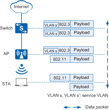
Figure 2 shows the process of directly forwarding service data packets.
In Figure 2, service data packets are not encapsulated in CAPWAP packets.
- In the uplink direction (from the STA to the Internet): When upstream service data packets in 802.11 format are sent from the STA to the AP, the AP converts the packets into 802.3 packets, tags the packets with VLAN s, and forwards the packets to the destination.
- In the downlink direction (from the Internet to the STA): When downstream service data packets in 802.3 format reach the AP (the packets are tagged with VLAN s' by upstream devices), the AP converts the 802.3 packets into 802.11 packets and forwards them to the STA.
Figure 3 shows the process of forwarding service data packets through CAPWAP tunnels.
In Figure 3, service data packets are encapsulated in CAPWAP packets and transmitted through CAPWAP data tunnels.
- In the uplink direction (from the STA to the Internet): When upstream service data packets in 802.11 format are sent from the STA to the AP, the AP converts the packets into 802.3 packets, tags the packets with VLAN s, and encapsulates them in CAPWAP packets. The upstream switch tags the packets with VLAN m. The AC decapsulates the CAPWAP packets and removes the tag VLAN m' from the packets.
- In the downlink direction (from the Internet to the STA): When downstream service data packets reach the AC, the AC encapsulates the packets in CAPWAP packets, allows the packets carrying VLAN s to pass through, and tags the packets with VLAN m'. The switch removes VLAN m from the packets. The AP decapsulates the CAPWAP packets, removes VLAN s, converts the 802.3 packets into 802.11 packets, and forwards them to the STA.
Management VLAN tag VLAN m is the outer tag of CAPWAP-encapsulated packets. The intermediate devices between the AC and AP can only transparently transmit packets carrying VLAN m and cannot be configured with VLAN s encapsulated in the CAPWAP packets.

Enabling the STP TC Protection Function
The STP function is enabled on an AC by default. STP can prevent network loops caused by incorrect connections or required by link backup.
When the STP topology changes, the device sends Topology Change (TC) packets to instruct other devices to update their forwarding tables. If network flapping occurs, the devices will receive a large number of TC packets in a short period of time, and update MAC address or ARP entries frequently. As a result, the devices are heavily burdened, threatening network stability.
The STP TC protection function is enabled by default. After enabling the TC protection function, you can set the number of times a switching device processes TC packets within a given time. If the number of TC packets received by the switching device within the given time exceeds the specified threshold, the switching device processes TC packets only for the specified number of times. For the TC packets exceeding the threshold, the switching device processes them together after the timer expires. In this way, the switching device is prevented from frequently deleting its MAC address and ARP entries, and therefore relieved from the ensuing burdens.
<HUAWEI> system-view
[HUAWEI] stp tc-protection
Disabling an AC from Responding to TC Packets, Enabling MAC-ARP Association, and Disabling IP Traffic Forwarding at Layer 2 During Link Switching on a Ring Network When the AC Functions As a Gateway
In normal cases, when STP detects network topology changes, the device sends TC packets to instruct its ARP module to age out or delete ARP entries. In this case, the device needs to learn ARP entries again to obtain the latest ARP entry information. However, if the network topology changes frequently or network devices on the network have a large number of ARP entries, ARP learning will increase the number of ARP packets. These ARP packets will occupy excessive system resources and affect running of other services.
To prevent this situation, you can disable APR tables from responding to TC packets. In this way, ARP entries of network devices on the network are not aged out or deleted even if the network topology changes. In addition, you can enable MAC address-triggered ARP entry update to prevent user service interruption even if ARP entries are not updated in a timely manner. In wireless scenarios, IP traffic forwarding at Layer 2 is not supported when links are switched on a ring network. Therefore, it is recommended that this function be disabled.
<HUAWEI> system-view
[HUAWEI] arp topology-change disable
<HUAWEI> system-view
[HUAWEI] mac-address update arp
<HUAWEI> system-view
[HUAWEI] ip forwarding converge normal
Configuring Port Isolation on Ports Connected to APs
In wireless application scenarios, APs typically do not need to access each other at Layer 2 or exchange broadcast packets. Therefore, you can configure port isolation on switch ports connected to APs. This function improves user communication security and prevents invalid broadcast packet data from being sent to the APs, ensuring the APs' forwarding performance and user services. In addition, port isolation needs to be configured for Layer 2 network devices connected to the AP gateway. For example, port isolation needs to be configured on the ports of aggregation switches connected to APs on the same Layer 2 network.
<HUAWEI> system-view
[HUAWEI] interface gigabitethernet 0/0/1
[HUAWEI-GigabitEthernet0/0/1] port-isolate enable group 1
User Isolation Is Recommended in Accounting Scenarios
In a traffic profile, user isolation prevents Layer 2 packets of all users from being forwarded to each other. That is, the users cannot communicate with each other after user isolation is enabled. This improves user communication security and enables the gateway to centrally forward user traffic, facilitating user accounting and management.
<HUAWEI> system-view
[HUAWEI] wlan
[HUAWEI-wlan-view] traffic-profile name traffic1
[HUAWEI-wlan-traffic-prof-traffic1] user-isolate l2
Warning: This action may cause service interruption. Continue?[Y/N]y
Enabling Optimized ARP Reply
When a stack functions as an access gateway, the stack can receive a large number of ARP packets requesting for the stack's interface MAC address. If all these ARP Request packets are sent to the master switch, the CPU usage of the switch increases, and other services are affected.
- When receiving an ARP Request packet of which the destination IP address is the local interface address, the switch where the interface is located directly returns an ARP Reply packet.
- When a stack system receives an ARP Request packet of which the destination IP address is not the local interface address and intra-VLAN proxy ARP is enabled on the master switch, the switch where the interface is located checks whether the ARP Request packet meets the proxy condition. If so, the switch returns an ARP Reply packet. If not, the switch discards the packet.
The optimized ARP reply function can be configured on a stand-alone fixed switch, but does not take effect.
- If the corresponding ARP entry exists, the stack performs optimized ARP reply to this ARP Request packet.
- If the corresponding ARP entry does not exist, the stack does not perform optimized ARP reply to this ARP Request packet.
- arp anti-attack gateway-duplicate enable: enables the ARP gateway anti-collision function.
- arp ip-conflict-detect enable: enables IP address conflict detection.
- arp anti-attack check user-bind enable: enables dynamic ARP inspection.
- dhcp snooping arp security enable: enables egress ARP inspection.
- arp over-vpls enable: enables ARP proxy on the device located on a VPLS network.
- arp-proxy enable: configures the routed ARP proxy function.
- ARP rate limiting based on source MAC addresses (configured using the arp speed-limit source-mac command)
- ARP rate limiting based on source IP addresses (configured using the arp speed-limit source-ip command)
- Global ARP rate limiting, ARP rate limiting in VLANs, as well as ARP rate limiting on interfaces (configured using the arp anti-attack rate-limit enable command)
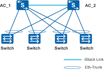
Reliability Configuration
ACs use iStack technology for networking, and access switches are connected to different members in the iStack through Eth-Trunks. If one AC is faulty, the network can be restored rapidly.
ARP Proxy Is Not Recommended When the AC Serves as a Gateway
The ARP proxy function increases the burden on the gateway, reducing the number of wireless users supported by the AC. It is recommended that the ARP proxy function be disabled when the AC serves as the gateway, unless otherwise required.
The AC Is Not Recommended as a DHCP Server
Wireless users roam, causing DHCP lease renewal (a short lease). This poses high requirements for the performance of the DHCP server. When the AC serves as a DHCP server, AC system performance is consumed, reducing the number of wireless users supported by the AC. Therefore, it is not recommended that the AC serve as both the gateway and DHCP server, unless otherwise required.
Properly Deploying eSight
If eSight is deployed, it periodically collects system data from the AC. In this case, you need to deploy Performance Management (PM) and set the collection interval to 30 minutes or longer.
<HUAWEI> system-view
[HUAWEI] pm
[HUAWEI-pm] statistics-task task1
[HUAWEI-pm-statistics-task1] sample-interval 30
PM technology periodically collects system data and consumes system resources. If eSight is not deployed, it is recommended that PM be disabled.