Example for Configuring Static Load Balancing
Static Load Balancing Overview
Load balancing can evenly distribute AP traffic loads to ensure sufficient bandwidth for each STA and to prevent a heavy load on a single AP. In static load balancing, APs are manually added to a load balancing group. When a STA wants to connect to an AP in this load balancing group, the AC uses a load balancing algorithm to determine whether to allow the STA to connect to the AP. If the connection is not allowed, the STA connects to a different AP with a lighter load.
Static load balancing can be used in scenarios such as conference rooms. For example, if two APs are deployed in a conference room, you can add the two APs to a load balancing group to prevent heavy load on a single AP.
Configuration Notes
For details about common WLAN configuration notes, see General Precautions for WLAN. For more deployment and configuration suggestions, see Wireless Network Deployment and Configuration Suggestions.
AP load balancing is not recommended.
After AP load balancing is configured, APs in the load balancing group forward received Probe packets to the AC. The AC then determines the APs from which STAs can access the WLAN. Too many Probe packets may degrade AC performance. Therefore, it is recommended that the AP load balancing function be disabled, unless otherwise required.
From V200R011C10, WLAN configurations are automatically delivered, without the need of running the commit all command.
In this example, the security policy is WPA2-PSK-AES. To ensure network security, choose an appropriate security policy according to your network configurations.
In tunnel forwarding mode, the management VLAN and service VLAN cannot be the same. If you set the forwarding mode to direct forwarding, you are not advised to configure the management VLAN and service VLAN to be the same.
In direct forwarding mode, configure port isolation on the interface directly connected to APs. If port isolation is not configured, many broadcast packets will be transmitted in the VLANs or WLAN users on different APs can directly communicate at Layer 2.
- Configure the management VLAN and service VLAN:
- In tunnel forwarding mode, service packets are encapsulated in a CAPWAP tunnel and forwarded to the AC. The AC then forwards the packets to the upper-layer network. Service packets and management packets can be forwarded normally only if the network between the AC and APs is added to the management VLAN and the network between the AC and upper-layer network is added to the service VLAN.
- In direct forwarding mode, service packets are not encapsulated into a CAPWAP tunnel, but are directly forwarded to the upper-layer network. Service packets and management packets can be forwarded normally only if the network between APs and upper-layer network is added to the service VLAN and the network between the AC and APs is added to the management VLAN.
- Each load balancing group supports a maximum of three APs.
- A load balancing group is a set of radios, and each radio can join only one load balancing group. If dual-band APs are used, traffic is load balanced among APs working on the same frequency band. That is, a dual-band AP can join two load balancing groups.
- All APs in a load balancing group work on the same frequency band (2.4 GHz or 5 GHz). AP radios in a load balancing group must have different channels configured and work on different channels.
- No ACK mechanism is provided for multicast packet transmission on air interfaces. In addition, wireless links are unstable. To ensure stable transmission of multicast packets, they are usually sent at low rates. If a large number of such multicast packets are sent from the network side, the air interfaces may be congested. You are advised to configure multicast packet suppression to reduce impact of a large number of low-rate multicast packets on the wireless network. Exercise caution when configuring the rate limit; otherwise, the multicast services may be affected.
- In direct forwarding mode, you are advised to configure multicast packet suppression on switch interfaces connected to APs.
- In tunnel forwarding mode, you are advised to configure multicast packet suppression in traffic profiles of the AC.
Networking Requirements
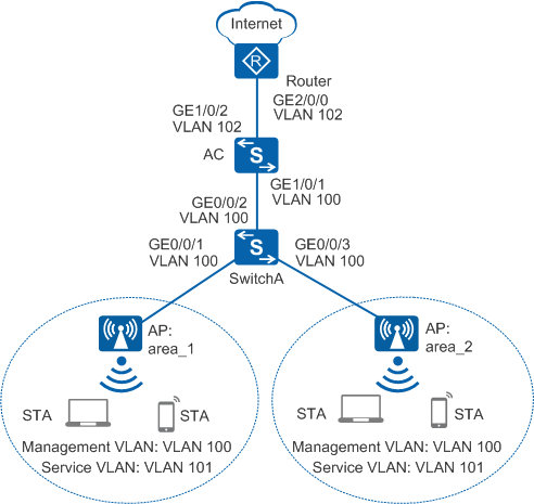
As shown in Figure 1, the AC connects to the upper layer network and manages the APs through the access and aggregation switches.
AP area_1 and AP area_2 are deployed in the same conference room. Traffic must be balanced on AP radios to prevent one AP radio from being heavily loaded.
The following uses an AC running V200R009C00 as an example. The key configurations vary in different versions. For details, see the Command Reference in the actual version.
Data Planning
Item |
Data |
|---|---|
DHCP server |
The AC functions as the DHCP server to assign IP addresses to the APs and STAs. |
IP address pool for the APs |
10.23.100.2-10.23.100.254/24 |
IP address pool for the STAs |
10.23.101.2-10.23.101.254/24 |
IP address of the AC's source interface |
VLANIF 100: 10.23.100.1/24 |
AP group |
|
Regulatory domain profile |
|
SSID profile |
|
Security profile |
|
VAP profile |
|
Static load balancing group |
|
Configuration Roadmap
- Configure the APs, AC, and upper-layer devices to communicate with each other.
- Configure the AC as a DHCP server to assign IP addresses to APs and STAs.
- Configure a VLAN pool for service VLANs.
- Configure the APs to go online.
- Create an AP group and add APs that require the same configuration to the group for unified configuration.
- Configure AC system parameters, including the country code and source interface used by the AC to communicate with the APs.
- Configure the AP authentication mode and import the APs offline to allow the APs to go online.
- Configure WLAN service parameters for STAs to access the WLAN.
- Configure static load balancing to prevent one AP from being heavily loaded.

During AP deployment, you can manually specify the working channels of the APs according to network planning or configure the radio calibration function to enable the APs to automatically select the optimal channels. This example configures the radio calibration function.
Procedure
- Set the NAC mode to unified mode on the AC (default setting). Configure SwitchA and the AC to allow the AP and AC to transmit CAPWAP packets.
# Add GE0/0/1 to GE0/0/3 on SwitchA to the management VLAN 100.
<HUAWEI> system-view
[HUAWEI] sysname SwitchA
[SwitchA] vlan batch 100
[SwitchA] interface gigabitethernet 0/0/1
[SwitchA-GigabitEthernet0/0/1] port link-type trunk
[SwitchA-GigabitEthernet0/0/1] port trunk pvid vlan 100
[SwitchA-GigabitEthernet0/0/1] port trunk allow-pass vlan 100
[SwitchA-GigabitEthernet0/0/1] undo port trunk allow-pass vlan 1
[SwitchA-GigabitEthernet0/0/1] stp edged-port enable
[SwitchA-GigabitEthernet0/0/1] port-isolate enable
[SwitchA-GigabitEthernet0/0/1] quit
[SwitchA] interface gigabitethernet 0/0/2
[SwitchA-GigabitEthernet0/0/2] port link-type trunk
[SwitchA-GigabitEthernet0/0/2] port trunk allow-pass vlan 100
[SwitchA-GigabitEthernet0/0/2] undo port trunk allow-pass vlan 1
[SwitchA-GigabitEthernet0/0/2] quit
[SwitchA] interface gigabitethernet 0/0/3
[SwitchA-gigabitethernet0/0/3] port link-type trunk
[SwitchA-GigabitEthernet0/0/3] port trunk pvid vlan 100
[SwitchA-gigabitethernet0/0/3] port trunk allow-pass vlan 100
[SwitchA-GigabitEthernet0/0/3] undo port trunk allow-pass vlan 1
[SwitchA-GigabitEthernet0/0/3] stp edged-port enable
[SwitchA-GigabitEthernet0/0/3] port-isolate enable
[SwitchA-gigabitethernet0/0/3] quit
# Add GE1/0/1 that connects the AC to SwitchA to VLAN 100.
<HUAWEI> system-view
[HUAWEI] sysname AC
[AC] vlan batch 100
[AC] interface gigabitethernet 1/0/1
[AC-GigabitEthernet1/0/1] port link-type trunk
[AC-GigabitEthernet1/0/1] port trunk allow-pass vlan 100
[AC-GigabitEthernet1/0/1] undo port trunk allow-pass vlan 1
[AC-GigabitEthernet1/0/1] quit
- Configure the AC to communicate with the upstream device.
# Configure VLANIF 101 (service VLAN) and VLANIF 102.
[AC] vlan batch 101 102
[AC] interface vlanif 101
[AC-Vlanif101] ip address 10.23.101.1 24
[AC-Vlanif101] quit
[AC] interface vlanif 102
[AC-Vlanif102] ip address 10.23.102.2 24
[AC-Vlanif102] quit
# Configure a default route on the AC.
[AC] ip route-static 0.0.0.0 0.0.0.0 10.23.102.1 //Configure a default route destined for Router.# Add GE1/0/2 that connects the AC to the Router to VLAN 102.
[AC] interface gigabitethernet 1/0/2
[AC-GigabitEthernet1/0/2] port link-type trunk
[AC-GigabitEthernet1/0/2] port trunk allow-pass vlan 102
[AC-GigabitEthernet1/0/2] undo port trunk allow-pass vlan 1
[AC-GigabitEthernet1/0/2] quit
- Configure the AC to assign an IP address to the AP and configure the Router to assign IP addresses to STAs.
# Configure the AC to assign an IP address to the AP from an interface IP address pool.
[AC] dhcp enable
[AC] interface vlanif 100
[AC-Vlanif100] ip address 10.23.100.1 24
[AC-Vlanif100] dhcp select interface  //Configure an interface-based address pool.
[AC-Vlanif100] quit
# Configure the AC as the DHCP relay agent and enable user entry detection on the AC.
[AC] interface vlanif 101
[AC-Vlanif101] dhcp select relay  //Configure the DHCP relay function.
[AC-Vlanif101] dhcp relay server-ip 10.23.102.1  //Set the DHCP server address for DHCP relay to 10.23.102.1, which resides on Router.
[AC-Vlanif101] quit
# Configure the Router as a DHCP server to assign IP addresses to STAs.
Configure the DNS server as required. The common methods are as follows:- In interface address pool scenarios, run the dhcp server dns-list ip-address &<1-8> command in the VLANIF interface view.
- In global address pool scenarios, run the dns-list ip-address &<1-8> command in the IP address pool view.
<Huawei> system-view
[Huawei] sysname Router
[Router] dhcp enable
[Router] ip pool sta  //Configure the address pool to assign IP addresses to STAs.
[Router-ip-pool-sta] gateway-list 10.23.101.1
[Router-ip-pool-sta] network 10.23.101.0 mask 24
[Router-ip-pool-sta] quit
[Router] vlan batch 102
[Router] interface vlanif 102
[Router-Vlanif102] ip address 10.23.102.1 24
[Router-Vlanif102] dhcp select global  //Configure a global address pool.
[Router-Vlanif102] quit
[Router] interface gigabitethernet 2/0/0
[Router-GigabitEthernet2/0/0] port link-type trunk
[Router-GigabitEthernet2/0/0] port trunk allow-pass vlan 102
[Router-GigabitEthernet2/0/0] undo port trunk allow-pass vlan 1
[Router-GigabitEthernet2/0/0] quit
[Router] ip route-static 10.23.101.0 24 10.23.102.2  //Configure a route on the Router destined for the network segment 10.23.101.0/24.
- Configure the APs to go online.
# Create an AP group.
[AC] wlan
[AC-wlan-view] ap-group name ap-group1
[AC-wlan-ap-group-ap-group1] quit
# Create a regulatory domain profile, configure the AC country code in the profile, and apply the profile to the AP group.
[AC-wlan-view] regulatory-domain-profile name domain1
[AC-wlan-regulate-domain-domain1] country-code cn
[AC-wlan-regulate-domain-domain1] quit
[AC-wlan-view] ap-group name ap-group1
[AC-wlan-ap-group-ap-group1] regulatory-domain-profile domain1 Warning: Modifying the country code will clear channel, power and antenna gain configurations of the radio and reset the AP. Continue?[Y/N]:y
[AC-wlan-ap-group-ap-group1] quit
[AC-wlan-view] quit
# Configure the AC's source interface.
[AC] capwap source interface vlanif 100
# Import APs offline on the WLAN AC and add APs area_1 and area_2 to AP group ap-group1. Assume that an AP's MAC address is 60de-4476-e360. Configure a name for the AP based on the AP's deployment location, so that you can know where the AP is deployed from its name. For example, name the AP area_1 if it is deployed in Area 1. The default AP authentication mode is MAC address authentication. If the default settings are retained, you do not need to run the ap auth-mode mac-auth command.
Each AP used in this example has two radios: radio 0 (2.4 GHz radio) and radio 1 (5 GHz radio).
[AC] wlan
[AC-wlan-view] ap auth-mode mac-auth
[AC-wlan-view] ap-id 0 ap-mac 60de-4476-e360
[AC-wlan-ap-0] ap-name area_1
[AC-wlan-ap-0] ap-group ap-group1 Warning: This operation may cause AP reset. If the country code changes, it will clear channel, power and antenna gain configuration s of the radio, Whether to continue? [Y/N]:y
[AC-wlan-ap-0] quit
[AC-wlan-view] ap-id 1 ap-mac dcd2-fc04-b500
[AC-wlan-ap-1] ap-name area_2
[AC-wlan-ap-1] ap-group ap-group1 Warning: This operation may cause AP reset. If the country code changes, it will clear channel, power and antenna gain configuration s of the radio, Whether to continue? [Y/N]:y
[AC-wlan-ap-1] quit
# Power on the AP and run the display ap all command to check the AP state. If the State field is displayed as nor, the AP has gone online.
[AC-wlan-view] display ap all
Total AP information:
nor  : normal          [2]
---------------------------------------------------------------------------------------
ID   MAC            Name   Group     IP             Type            State STA Uptime
---------------------------------------------------------------------------------------
0    60de-4476-e360 area_1 ap-group1 10.23.101.253  AP5030DN        nor   0   5M:2S
1    dcd2-fc04-b500 area_2 ap-group1 10.23.101.254  AP5030DN        nor   0   5M:4S
---------------------------------------------------------------------------------------
Total: 2
- Configure WLAN service parameters.# Create security profile wlan-security and set the security policy in the profile.
In this example, the security policy is set to WPA2+PSK+AES and password to a1234567. In actual situations, the security policy must be configured according to service requirements.
[AC-wlan-view] security-profile name wlan-security
[AC-wlan-sec-prof-wlan-security] security wpa2 psk pass-phrase a1234567 aes  //Configure security policy WPA2+PSK+AES.
[AC-wlan-sec-prof-wlan-security] quit
# Create SSID profile wlan-ssid and set the SSID name to wlan-net.
[AC-wlan-view] ssid-profile name wlan-ssid
[AC-wlan-ssid-prof-wlan-ssid] ssid wlan-net  //Set the SSID to wlan-net.
[AC-wlan-ssid-prof-wlan-ssid] quit
# Create VAP profile wlan-vap, set the data forwarding mode and service VLAN, and apply the security profile and SSID profile to the VAP profile.
[AC-wlan-view] vap-profile name wlan-vap
[AC-wlan-vap-prof-wlan-vap] forward-mode tunnel  //Set the service forwarding mode to tunnel.
[AC-wlan-vap-prof-wlan-vap] service-vlan vlan-id 101  //Set the VLAN ID to 101. By default, the VLAN ID is 1.
[AC-wlan-vap-prof-wlan-vap] security-profile wlan-security
[AC-wlan-vap-prof-wlan-vap] ssid-profile wlan-ssid
[AC-wlan-vap-prof-wlan-vap] quit
# Bind VAP profile wlan-vap to the AP group and apply the profile to radio 0 and radio 1 of the AP.
[AC-wlan-view] ap-group name ap-group1
[AC-wlan-ap-group-ap-group1] vap-profile wlan-vap wlan 1 radio 0
[AC-wlan-ap-group-ap-group1] vap-profile wlan-vap wlan 1 radio 1
[AC-wlan-ap-group-ap-group1] quit
- Configure static load balancing.
# Create the static load balancing group and set the start threshold for static load balancing to 15 and the load difference threshold to 25%.
[AC-wlan-view] sta-load-balance static-group name wlan-static  //Create load balancing group wlan-static.
[AC-wlan-sta-lb-static-wlan-static] start-threshold 15  //Set the start threshold for load balancing (based on the number of users) to 15. The default value is 10.
[AC-wlan-sta-lb-static-wlan-static] gap-threshold 25  //Set the load difference threshold for load balancing (based on the number of users) to 25%. The default value is 20%.
From V200R011C00 to V200R019C00, the device supports static load balancing based on channel usage. Configure static load balancing based on the number of users as follows:
[AC-wlan-view] sta-load-balance static-group name wlan-static
[AC-wlan-sta-lb-static-wlan-static] mode sta-number  //Configure static load balancing based on the number of users. By default, static load balancing based on the number of users is used.
[AC-wlan-sta-lb-static-wlan-static] sta-number start-threshold 15
[AC-wlan-sta-lb-static-wlan-static] sta-number gap-threshold 25  //In V200R011C10 and later versions, the format is changed to sta-number gap-threshold percentage 25.
In V200R019C10 and later versions, the device does not support static load balancing based on channel usage. Configure static load balancing based on the number of users as follows:
[AC-wlan-view] sta-load-balance static-group name wlan-static
[AC-wlan-sta-lb-static-wlan-static] sta-number start-threshold 15
[AC-wlan-sta-lb-static-wlan-static] sta-number gap-threshold percentage 25
# Add AP area_1 and AP area_2 to the static load balancing group.
[AC-wlan-sta-lb-static-wlan-static] member ap-name area_1  //Add AP area_1 to load balancing group wlan-static.
[AC-wlan-sta-lb-static-wlan-static] member ap-name area_2
[AC-wlan-sta-lb-static-wlan-static] quit
- Commit the configuration.
[AC-wlan-view] commit all
Warning: Committing configuration may cause service interruption, continue?[Y/N]:y
- Verify the configuration.
Connect STAs to the WLAN with SSID wlan-net and enter the password a1234567. Run the display station ssid wlan-net command on the AC. The command output shows that the STAs are connected to the WLAN wlan-net.
[AC-wlan-view] display station ssid wlan-net
Rf/WLAN: Radio ID/WLAN ID
Rx/Tx: link receive rate/link transmit rate(Mbps)
-------------------------------------------------------------------------------------
STA MAC          AP ID Ap name Rf/WLAN  Band  Type  Rx/Tx  RSSI  VLAN  IP address
-------------------------------------------------------------------------------------
e019-1dc7-1e08   0     area_1   0/1     2.4G  11n   65/38  -29   101   10.23.101.253
b878-2eb4-2689   1     area_2   0/1     2.4G  11n   78/43  -33   101   10.23.101.254
-------------------------------------------------------------------------------------
Total: 2 2.4G: 2 5G: 0
Run the display sta-load-balance static-group name wlan-static command on the AC to check the static load balancing configuration.
[AC-wlan-view] display sta-load-balance static-group name wlan-static
------------------------------------------------------------
Group name           : wlan-static
Load-balance status  : balance
Start threshold      : 15
Gap threshold(%)     : 25
Deny threshold       : 3
------------------------------------------------------------
RfID: Radio ID
CurEIRP: Current EIRP (dBm)
Act CH: Actual channel, Cfg CH: Config channel
------------------------------------------------------------
AP ID  AP Name  RfID  Act CH/Cfg CH  CurEIRP/MaxEIRP  Client
------------------------------------------------------------
0      area_1   0     6/-            20/28            1
0      area_1   1     153/-          29/29            0
1      area_2   0     1/-            20/28            1
1      area_2   1     149/-          29/29            0
------------------------------------------------------------
Total: 4
- When a new STA requests to connect to AP area_1, the AC uses a static load balancing algorithm to redirect the STA to a lightly loaded AP in the same load balancing group.
Configuration Files
SwitchA configuration file
#
sysname SwitchA
#
vlan batch 100
#
interface gigabitethernet0/0/1
 port link-type trunk
 port trunk pvid vlan 100
 undo port trunk allow-pass vlan 1
 port trunk allow-pass vlan 100
 stp edged-port enable
 port-isolate enable group 1
#
interface gigabitethernet0/0/2
 port link-type trunk
 undo port trunk allow-pass vlan 1
 port trunk allow-pass vlan 100
#
interface gigabitethernet0/0/3
 port link-type trunk
 undo port trunk allow-pass vlan 1
 port trunk allow-pass vlan 100
 stp edged-port enable
 port-isolate enable group 1
#
return
Router configuration file
#
sysname Router
#
vlan batch 102
#
dhcp enable
#
ip pool sta
 gateway-list 10.23.101.1
 network 10.23.101.0 mask 255.255.255.0
#
interface Vlanif102
 ip address 10.23.102.1 255.255.255.0
 dhcp select global
#
interface GigabitEthernet2/0/0
 port link-type trunk
 undo port trunk allow-pass vlan 1
 port trunk allow-pass vlan 102
#
ip route-static 10.23.101.0 255.255.255.0 10.23.102.2
#
return
AC configuration file
#
sysname AC
#
vlan batch 100 to 102
#
dhcp enable
#
interface Vlanif100
 ip address 10.23.100.1 255.255.255.0
 dhcp select interface
#
interface Vlanif101
 ip address 10.23.101.1 255.255.255.0
 dhcp select relay
 dhcp relay server-ip 10.23.102.1
#
interface Vlanif102
 ip address 10.23.102.2 255.255.255.0
#
interface GigabitEthernet1/0/1
 port link-type trunk
 undo port trunk allow-pass vlan 1
 port trunk allow-pass vlan 100
#
interface GigabitEthernet1/0/2
 port link-type trunk
 undo port trunk allow-pass vlan 1
 port trunk allow-pass vlan 102
#
ip route-static 0.0.0.0 0.0.0.0 10.23.102.1
#
capwap source interface vlanif100
#
wlan
 security-profile name wlan-security
  security wpa2 psk pass-phrase %^%#m"tz0f>~7.[`^6RWdzwCy16hJj/Mc!,}s`X*B]}A%^%# aes
 ssid-profile name wlan-ssid
  ssid wlan-net
 vap-profile name wlan-vap
  forward-mode tunnel
  service-vlan vlan-id 101
  ssid-profile wlan-ssid
  security-profile wlan-security
 sta-load-balance static-group name wlan-static
  gap-threshold 25
  member ap-name area_1 radio 0
  member ap-name area_1 radio 1
  member ap-name area_2 radio 0
  member ap-name area_2 radio 1
  start-threshold 15
 regulatory-domain-profile name domain1
 ap-group name ap-group1
  regulatory-domain-profile domain1
  vap-profile wlan-vap wlan 1
  radio 0
   vap-profile wlan-vap wlan 1
  radio 1
   vap-profile wlan-vap wlan 1
ap-id 0 type-id 19 ap-mac 60de-4476-e360 ap-sn 210235554710CB000042
  ap-name area_1
  ap-group ap-group1
ap-id 1 type-id 21 ap-mac dcd2-fc04-b500 ap-sn 210235554710CB000078
  ap-name area_2
  ap-group ap-group1
#
return