Example for Configuring the WLAN Service Using WDS Technology
WDS Overview
A wireless distribution system (WDS) connects two or more wired or wireless LANs using wireless links to establish a large network.
On a traditional WLAN network, APs connect to an AC through wired uplinks. However, wired connections are difficult or costly to implement in areas where network cables are difficult to deploy, such as tunnels and docks. WDS technology connects APs to an AP using wireless links to facilitate WLAN deployment in complex geographical environments, reduce network deployment cost, allow flexible networking, and make the network easy to expand.
- Root: A root AP connects to an AC using a wired link and connects to a middle or leaf AP using a wireless uplink.
- Middle: A middle AP is an intermediate node using wireless links to connect an upstream root AP and a downstream leaf AP.
- Leaf: A leaf AP connects to a root or middle AP using an uplink wireless link.
Both WDS and mesh technologies can implement wireless bridging between APs. A WDS network supports a maximum of three hops (for example, a WDS link can be established along a root node, a middle node, and a leaf node), has a tree topology, and does not support link redundancy between nodes. On the other hand, a mesh network supports a maximum of eight hops, has a mesh topology, and supports link redundancy between nodes. These factors make a mesh network more reliable than a WDS network. You can choose the WDS or mesh technology to deploy wireless bridging between APs according to your networking needs.
Configuration Notes
The AP2030DN, AP7030DE, AP9330DN, AP6310SN-GN and AP2010DN do not support the WDS function.
- On a WDS or mesh network, an 802.11ac AP cannot interoperate with non-802.11ac APs regardless of their radio types. Only 802.11ac APs can interoperate with each other.
 Among all WDS- and mesh-capable APs, only the AP4050DN, AP4051DN, AP4151DN, AP8050DN, AP8150DN, AP5030DN, AP5130DN, AP8130DN, AP8030DN, AP8130DN-W, AP4030DN, AP4130DN, AP9131DN, AP9132DN, AP6050DN, AP6150DN, AP7050DE, AP7050DN-E, AP4030TN, AP4050DN-E, and AP4050DN-HD are 802.11ac APs.
 If radio 0 of the AP8130DN is configured to work on the 5 GHz frequency band and used for WDS or mesh services, the software version of the AP connected to the AP8130DN must be V200R005C10 or later.
- When planning a WDS network, pay attention to the following:
- The back-to-back WDS networking involves two WDS networks. A single WDS network cannot form a back-to-back WDS network.
- Only one root node exists on the WDS network.
- A middle node sets up WDS links only with the leaf node and root node. Middle nodes do not set up WDS links between each other.
- Three hops are recommended for each WDS link (a 3-hop WDS link includes a root node, a middle node, and a leaf node).
- Each node on the WDS link supports a maximum of six subnodes.
APs supporting WDS can be interconnected. APs with 802.11ac and 802.11n chips are not subject to interoperation constraints.
- You cannot use WDS and mesh technologies on the same network.
If WDS and Mesh services are configured on an AP radio, WIDS, spectrum analysis, or WLAN location on the radio does not take effect.
- How to configure the source interface:
- In V200R006, run the wlan ac source interface { loopback loopback-number | vlanif vlan-id } command in the WLAN view.
- In V200R007 and V200R008, run the capwap source interface { loopback loopback-number | vlanif vlan-id } command in the system view.
- The following table lists applicable products and versions.
Table 1 Applicable products and versions Software Version
Product Model
AP Model and Version
V200R005C00
S7700, S9700
V200R005C00:
AP3010DN-AGN, AP5010DN-AGN, AP5010SN-GN, AP5030DN, AP5130DN, AP6010SN-GN, AP6010DN-AGN, AP6510DN-AGN, AP6610DN-AGN, AP7110DN-AGN, AP7110SN-GN
V200R006C00
S5720-HI, S7700, S9700
V200R005C00:
AP3010DN-AGN, AP5010DN-AGN, AP5010SN-GN, AP5030DN, AP5130DN, AP6010SN-GN, AP6010DN-AGN, AP6510DN-AGN, AP6610DN-AGN, AP7110DN-AGN, AP7110SN-GN
V200R007C00
S5720-HI, S7700, S9700
V200R005C10:
AP3010DN-AGN, AP5010DN-AGN, AP5010SN-GN, AP5030DN, AP5130DN, AP6010SN-GN, AP6010DN-AGN, AP6510DN-AGN, AP6610DN-AGN, AP7110DN-AGN, AP7110SN-GN, AP8030DN, AP8130DN
V200R008C00
S5720-HI, S7700, S9700
V200R005C10:
AP3010DN-AGN, AP5010DN-AGN, AP5010SN-GN, AP5030DN, AP5130DN, AP6010SN-GN, AP6010DN-AGN, AP6510DN-AGN, AP6610DN-AGN, AP7110DN-AGN, AP7110SN-GN, AP8030DN, AP8130DN
V200R005C30:
AP4030DN, AP4130DN
Networking Requirements
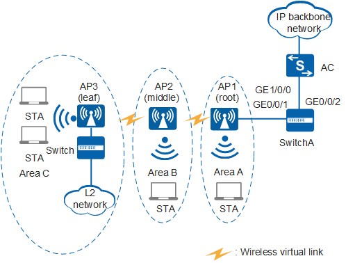
An enterprise has three office locations: Area A, Area B, and Area C. AP1 in Area A can connect to SwitchA through cables, but AP2 in Area B and AP3 in Area C cannot. The enterprise needs to provide Internet access for WLAN users in the three areas and wired users in Area C, as shown in Figure 1.
Data Planning
Before configuring the WDS service, determine the types and MAC addresses of the APs used as WDS bridges. The following table provides the data plan for this example.
AP |
Type |
MAC |
|---|---|---|
AP1 |
AP6010DN-AGN |
0046-4b59-1ee0 |
AP2 |
AP6010DN-AGN |
0046-4b59-1d20 |
AP3 |
AP6010DN-AGN |
0046-4b59-1d40 |
The following provides data planning for mesh service configuration.
Item |
Data |
Description |
|---|---|---|
VLAN |
Management VLAN: 100 |
None |
Service VLANs: 101, 102, 103, 104, 105, 106
|
The WDS bridges must allow packets of service VLANs to which Area A, Area B, and Area C belong to pass through. |
|
Service forwarding mode on APs |
Direct forwarding mode |
None |
IP address of the AC's source interface |
VLANIF 100: 192.168.10.1/24 |
None |
AP region |
AP1: 101, AP2: 102, AP3: 103 |
None |
WMM profile |
Name: wp01 |
None |
Radio profile |
Name: rp01 and rp02 |
Use radio profile rp02 for the WDS service and radio profile rp01 for the basic WLAN service. |
Security profile |
|
WDS bridges support only the security policy using WPA2+PSK authentication and CCMP encryption. In this example, the security profile sp01 is also used for the basic WLAN service. Select an appropriate security policy for the WLAN service in real world applications. |
Traffic profile |
Name: tp01 |
None |
Bridge profile |
|
All APs on a WDS network must have the same bridge ID. |
Service set |
|
None |
|
None |
|
|
None |
|
Bridge whitelist |
Name: bw01 and bw02 |
A WDS whitelist profile contains MAC addresses of neighboring APs allowed to set up WDS links with an AP. After a WDS whitelist profile is applied to an AP radio, only APs with MAC addresses in the whitelist can access the AP, and other APs are denied. In the WDS, only APs with radios working in root mode and middle mode can have a whitelist configured. APs in leaf mode require no whitelist. |
Configuration Roadmap
The configuration roadmap is as follows:
- Configure the AC and SwitchA to implement Layer 2 connectivity between the AC, SwitchA, and AP1.
- Configure the WDS function to allow AP2 and AP3 to connect to the AC using wireless links.
- Configure the basic WLAN service to provide Internet access service for WLAN users in Area A, Area B, and Area C.
Procedure
- Connect AC and AP1.
# Configure the access switch SwitchA. Add GE0/0/1 on SwitchA to VLAN 100 (management VLAN), and set the PVID of GE0/0/1 to VLAN 100. Configure GE0/0/1 and GE0/0/2 to allow packets from VLANs 100 to 106 to pass through.
Configure port isolation on GE0/0/1 that connects SwitchA and AP. Otherwise, unnecessary packets are broadcast in the VLAN or WLAN users of different APs can communicate with each other at Layer 2.
<HUAWEI> system-view
[HUAWEI] sysname SwitchA
[SwitchA] vlan batch 100 to 106
[SwitchA] interface gigabitEthernet 0/0/1
[SwitchA-GigabitEthernet0/0/1] port link-type trunk
[SwitchA-GigabitEthernet0/0/1] port trunk pvid vlan 100
[SwitchA-GigabitEthernet0/0/1] port trunk allow-pass vlan 100 to 106
[SwitchA-GigabitEthernet0/0/1] port-isolate enable       //If the port isolation group is not specified, the interface is added to port isolation group 1 by default.
[SwitchA-GigabitEthernet0/0/1] quit
[SwitchA] interface gigabitEthernet 0/0/2
[SwitchA-GigabitEthernet0/0/2] port link-type trunk
[SwitchA-GigabitEthernet0/0/2] port trunk allow-pass vlan 100 to 106
[SwitchA-GigabitEthernet0/0/2] quit
# Set the NAC mode to unified mode on the AC (default setting). Configure GE1/0/0 to allow packets from VLANs 100 to 106 to pass through.
[HUAWEI] sysname AC [AC] vlan batch 100 to 106 [AC] interface gigabitEthernet 1/0/0 [AC-GigabitEthernet1/0/0] port link-type trunk [AC-GigabitEthernet1/0/0] port trunk allow-pass vlan 100 to 106 [AC-GigabitEthernet1/0/0] quit - Configure the AC to allocate IP addresses for APs and STAs.
# Configure AC as a DHCP server to allocate IP addresses to APs and STAs using an address pool.
[AC] dhcp enable
[AC] interface vlanif 100
[AC-Vlanif100] ip address 192.168.10.1 24
[AC-Vlanif100] dhcp select interface
[AC-Vlanif100] quit
[AC] interface vlanif 101
[AC-Vlanif101] ip address 192.168.1.1 24
[AC-Vlanif101] dhcp select interface
[AC-Vlanif101] quit
[AC] interface vlanif 102
[AC-Vlanif102] ip address 192.168.2.1 24
[AC-Vlanif102] dhcp select interface
[AC-Vlanif102] quit
[AC] interface vlanif 103
[AC-Vlanif103] ip address 192.168.3.1 24
[AC-Vlanif103] dhcp select interface
[AC-Vlanif103] quit
- Configure AC system parameters.
# Configure the country code.
[AC] wlan ac-global country-code cn
Warning: Modify the country code may delete configuration on those AP which use
the global country code and reset them, continue?[Y/N]:y
# Configure the AC ID and carrier ID.
[AC] wlan ac-global ac id 1 carrier id other //The default AC ID is 0. Set the AC ID to 1.# Configure the source interface.
[AC] wlan
[AC-wlan-view] wlan ac source interface vlanif 100
- Configure the AC to manage APs.
[AC-wlan-view] ap id 1 ap-type AP6010DN-AGN mac 0046-4b59-1ee0
[AC-wlan-ap-1] quit
[AC-wlan-view] ap id 2 ap-type AP6010DN-AGN mac 0046-4b59-1d20
[AC-wlan-ap-2] quit
[AC-wlan-view] ap id 3 ap-type AP6010DN-AGN mac 0046-4b59-1d40
[AC-wlan-ap-3] quit
# Create AP regions 101, 102, and 103. An AC has a default AP region with the ID 0. AP regions 101, 102, and 103 are used as an example here.
[AC-wlan-view] ap-region id 101
[AC-wlan-ap-region-101] quit
[AC-wlan-view] ap-region id 102
[AC-wlan-ap-region-102] quit
[AC-wlan-view] ap-region id 103
[AC-wlan-ap-region-103] quit
# Add AP1 to AP region 101, AP2 to AP region 102, and AP3 to AP region 103. By default, an AP is added to region 0. This example adds the three APs to regions 101, 102, and 103 respectively.
[AC-wlan-view] ap id 1
[AC-wlan-ap-1] region-id 101
[AC-wlan-ap-1] quit
[AC-wlan-view] ap id 2
[AC-wlan-ap-2] region-id 102
[AC-wlan-ap-2] quit
[AC-wlan-view] ap id 3
[AC-wlan-ap-3] region-id 103
[AC-wlan-ap-3] quit
- Set WDS bridge parameters.
# Create a WMM profile named wp01 and retain the default settings in the profile.
[AC-wlan-view] wmm-profile name wp01
[AC-wlan-wmm-prof-wp01] quit
# Create a radio profile rp02 for the WDS bridges, set the channel mode to fixed and retain the default settings for other parameters, and bind the WMM profile wp01 to the radio profile. The default channel mode is auto, but the fixed mode must be used in this example.
[AC-wlan-view] radio-profile name rp02 id 1
[AC-wlan-radio-prof-rp02] wmm-profile name wp01
[AC-wlan-radio-prof-rp02] channel-mode fixed     // The APs along the WDS link must use the same channel, so the fixed mode must be used.
[AC-wlan-radio-prof-rp02] quit
# Create the bridge whitelists bw01 and bw02. By default, no bridge whitelist is created. This example uses whitelist bw01 for the root node and whitelist bw02 for the middle node to control the connection between neighboring APs.
[AC-wlan-view] bridge-whitelist name bw01
[AC-wlan-br-whitelist-bw01] peer ap mac 0046-4b59-1d20       // The middle AP needs to connect to the root AP, so AP2's MAC address is added to bw01.
[AC-wlan-br-whitelist-bw01] quit
[AC-wlan-view] bridge-whitelist name bw02
[AC-wlan-br-whitelist-bw02] peer ap mac 0046-4b59-1d40       // The leaf AP needs to connect to the middle AP, so AP3's MAC address is added to bw01.
[AC-wlan-br-whitelist-bw02] quit
# Bind the radio profile rp02 to radio 1 of AP1, set the bridge mode of radio 1 to root, and bind the bridge whitelist bw01 to radio 1. By default, no bridge whitelist is bound to a radio. This example binds bridge whitelist bw01 to the root AP's radio.
[AC-wlan-view] ap 1 radio 1
[AC-wlan-radio-1/1] radio-profile name rp02
[AC-wlan-radio-1/1] bridge enable mode root
[AC-wlan-radio-1/1] bridge-whitelist name bw01
[AC-wlan-radio-1/1] bridge whitelist enable
[AC-wlan-radio-1/1] quit
# Bind the radio profile rp02 to radio 1 of AP2, set the bridge mode of radio 1 to middle, and bind the bridge whitelist bw02 to radio 1. By default, no bridge whitelist is bound to a radio. This example binds bridge whitelist bw02 to the middle AP's radio.
[AC-wlan-view] ap 2 radio 1
[AC-wlan-radio-2/1] radio-profile name rp02
[AC-wlan-radio-2/1] bridge enable mode middle
[AC-wlan-radio-2/1] bridge-whitelist name bw02
[AC-wlan-radio-2/1] bridge whitelist enable
[AC-wlan-radio-2/1] quit
# Bind AP3 radio 1 to the radio profile rp02 and set the wireless bridge working mode to leaf.
[AC-wlan-view] ap 3 radio 1
[AC-wlan-radio-3/1] radio-profile name rp02
[AC-wlan-radio-3/1] bridge enable mode leaf
[AC-wlan-radio-3/1] quit
# After the preceding configurations are complete, power on the APs. If the APs are already powered on, restart the root AP to make the configuration take effect. Run the display ap all and display bridge-link all commands on the AC to check whether the APs work properly and whether WVLs are successfully established. If the WVLs are displayed and the states of all the APs are normal, the management bridge is successfully established.
[AC-wlan-view] display ap all
  All AP information:
  Normal[3],Fault[0],Commit-failed[0],Committing[0],Config[0],Download[0]
  Config-failed[0],Standby[0],Type-not-match[0],Ver-mismatch[0]
  ------------------------------------------------------------------------------
  AP    AP                    AP              Profile   AP              AP
                                              /Region
  ID    Type                  MAC             ID        State           Sysname
  ------------------------------------------------------------------------------
  1     AP6010DN-AGN          0046-4b59-1ee0    0/101   normal          ap-1
  2     AP6010DN-AGN          0046-4b59-1d20    0/102   normal          ap-2
  3     AP6010DN-AGN          0046-4b59-1d40    0/103   normal          ap-3
  ------------------------------------------------------------------------------
  Total number: 3,printed: 3
[AC-wlan-view] display bridge-link all ------------------------------------------------------------------------------ AP ID AP MAC Radio ID Coverage Distance(100m) Channel Bridge Work Mode Peer AP MAC Peer AP ID Peer AP Status RSSI(dBm) Max RSSI(dBm) ------------------------------------------------------------------------------ 1 0046-4b59-1ee0 1 3 149 root 0046-4b59-1d20 2 normal -33 -32 2 0046-4b59-1d20 1 3 149 middle 0046-4b59-1ee0 1 normal -31 -31 2 0046-4b59-1d20 1 3 149 middle 0046-4b59-1d40 3 normal -33 -32 3 0046-4b59-1d40 1 3 149 leaf 0046-4b59-1d20 2 normal -31 -31 ------------------------------------------------------------------------------ Total: 4 - Configure a radio profile and a WLAN-ESS interface.
# Create the radio profile rp01 for user services, use the default settings, and bind the radio profile to the WMM profile wp01.
[AC-wlan-view] radio-profile name rp01 id 0
[AC-wlan-radio-prof-rp01] wmm-profile name wp01
[AC-wlan-radio-prof-rp01] quit
[AC-wlan-view] quit
# Create three WLAN-ESS interfaces.
[AC] interface wlan-ess 1
[AC-Wlan-Ess1] port trunk allow-pass vlan 101
[AC-Wlan-Ess1] quit
[AC] interface wlan-ess 2
[AC-Wlan-Ess2] port trunk allow-pass vlan 102
[AC-Wlan-Ess2] quit
[AC] interface wlan-ess 3
[AC-Wlan-Ess3] port trunk allow-pass vlan 103
[AC-Wlan-Ess3] quit
- Configure the bridge profile and service set.
# Create security profile sp01, set the security and authentication policy to WPA2-PSK, set the authentication key to huawei123, and set the encryption mode to CCMP.
The AP that establishes the bridge on a WDS network supports only WPA2+PSK+CCMP.[AC] wlan [AC-wlan-view] security-profile name sp01 [AC-wlan-sec-prof-sp01] security-policy wpa2 [AC-wlan-sec-prof-sp01] wpa2 authentication-method psk pass-phrase cipher huawei123 encryption-method ccmp [AC-wlan-sec-prof-sp01] quit
# Create a bridge profile with the name bp01 and identifier ChinaNet01, and bind the bridge profile to the security profile sp01.
[AC-wlan-view] bridge-profile name bp01
[AC-wlan-bridge-prof-bp01] bridge-name ChinaNet01
[AC-wlan-bridge-prof-bp01] vlan tagged 101 to 106       // Allow packets of service VLANs to pass.
[AC-wlan-bridge-prof-bp01] security-profile name sp01
[AC-wlan-bridge-prof-bp01] quit
# Create traffic profile tp01 and use the default settings.
[AC-wlan-view] traffic-profile name tp01
[AC-wlan-traffic-prof-tp01] quit
# Create and configure a service set ss01 and SSID ChinaSer01.
[AC-wlan-view] service-set name ss01
[AC-wlan-service-set-ss01] traffic-profile name tp01
[AC-wlan-service-set-ss01] security-profile name sp01
[AC-wlan-service-set-ss01] ssid ChinaSer01
[AC-wlan-service-set-ss01] service-vlan 101       // Change the VLAN ID of the service set to 101. (The default VLAN ID is 1.)
[AC-wlan-service-set-ss01] wlan-ess 1
[AC-wlan-service-set-ss01] quit
# Create and configure a service set ss02 and SSID ChinaSer02.
[AC-wlan-view] service-set name ss02
[AC-wlan-service-set-ss02] traffic-profile name tp01
[AC-wlan-service-set-ss02] security-profile name sp01
[AC-wlan-service-set-ss02] ssid ChinaSer02
[AC-wlan-service-set-ss02] service-vlan 102       // Change the VLAN ID of the service set to 102. (The default VLAN ID is 1.)
[AC-wlan-service-set-ss02] wlan-ess 2
[AC-wlan-service-set-ss02] quit
# Create and configure a service set ss03 and SSID ChinaSer03.
[AC-wlan-view] service-set name ss03
[AC-wlan-service-set-ss03] traffic-profile name tp01
[AC-wlan-service-set-ss03] security-profile name sp01
[AC-wlan-service-set-ss03] ssid ChinaSer03
[AC-wlan-service-set-ss03] service-vlan 103       //  Change the VLAN ID of the service set to 103. (The default VLAN ID is 1.)
[AC-wlan-service-set-ss03] wlan-ess 3
[AC-wlan-service-set-ss03] quit
# Create a bridge VAP on AP1 radio 1 and bind the radio to the bridge profile. Create a service VAP on AP1 radio 0 and bind the radio to the radio profile and service set.
[AC-wlan-view] ap 1 radio 0
[AC-wlan-radio-1/0] radio-profile name rp01
[AC-wlan-radio-1/0] service-set name ss01
[AC-wlan-radio-1/0] quit
[AC-wlan-view] ap 1 radio 1
[AC-wlan-radio-1/1] bridge-profile name bp01
[AC-wlan-radio-1/1] channel 40mhz-plus 157      // Radios that establish a WDS link must use the same channel and bandwidth. Here, the radios use 40 MHz bandwidth and channel 157.
[AC-wlan-radio-1/1] quit
# Create a bridge VAP on AP2 radio 1 and bind the radio to the bridge profile. Create a service VAP on AP2 radio 0 and bind the radio to the radio profile and service set.
[AC-wlan-view] ap 2 radio 0
[AC-wlan-radio-2/0] radio-profile name rp01
[AC-wlan-radio-2/0] service-set name ss02
[AC-wlan-radio-2/0] quit
[AC-wlan-view] ap 2 radio 1
[AC-wlan-radio-2/1] bridge-profile name bp01
[AC-wlan-radio-2/1] channel 40mhz-plus 157
[AC-wlan-radio-2/1] quit
# Create a bridge VAP on AP3 radio 0 and bind the radio to the bridge profile. Create a service VAP on AP3 radio 0 and bind the radio to the radio profile and service set.
[AC-wlan-view] ap 3 radio 0
[AC-wlan-radio-3/0] radio-profile name rp01
[AC-wlan-radio-3/0] service-set name ss03
[AC-wlan-radio-3/0] quit
[AC-wlan-view] ap 3 radio 1
[AC-wlan-radio-3/1] bridge-profile name bp01
[AC-wlan-radio-3/1] channel 40mhz-plus 157
[AC-wlan-radio-3/1] quit
- Configure APs' wired interfaces.
# Set parameters for the AP3 wired interface.
[AC-wlan-view] ap id 3
[AC-wlan-ap-3] lineate-port gigabitethernet 0 mode endpoint     // On a WDS network, downlink wired interfaces of APs must be set to the endpoint mode.
[AC-wlan-ap-3] lineate-port gigabitethernet 0 vlan tagged 104 to 106     // Add the AP's wired interface to VLANs 104, 105, and 106 in tagged mode.
[AC-wlan-ap-3] quit
After changing the working mode of AP wired interfaces, reset the APs to make the configurations take effect.
- Deliver parameters to APs.
# Deliver the AP parameters on the AC for the configurations to take effect.
[AC-wlan-view] commit ap 3
Warning: Committing configuration may cause service interruption, continue?[Y/N]y
[AC-wlan-view] commit ap 2
Warning: Committing configuration may cause service interruption, continue?[Y/N]y
[AC-wlan-view] commit ap 1
Warning: Committing configuration may cause service interruption, continue?[Y/N]y
- Verify the configuration.
WLAN users in areas A, B, and C and wired users in area C can access the Internet.
Configuration Files
SwitchA configuration file
#
sysname SwitchA
#
 vlan batch 100 to 106
#
interface GigabitEthernet0/0/1
 port link-type trunk
 port trunk pvid vlan 100
 port trunk allow-pass vlan 100 to 106
 port-isolate enable group 1
#
interface GigabitEthernet0/0/2
 port link-type trunk
 port trunk allow-pass vlan 100 to 106
#
return
AC configuration file
#
sysname AC
#
vlan batch 100 to 106
#
wlan ac-global carrier id other ac id 1
#
dhcp enable
#
interface Vlanif100
 ip address 192.168.10.1 255.255.255.0
 dhcp select interface
#
interface Vlanif101
 ip address 192.168.1.1 255.255.255.0
 dhcp select interface
#
interface Vlanif102
 ip address 192.168.2.1 255.255.255.0
 dhcp select interface
#
interface Vlanif103
 ip address 192.168.3.1 255.255.255.0
 dhcp select interface
#
interface GigabitEthernet1/0/0
 port link-type trunk
 port trunk allow-pass vlan 100 to 106
#
interface Wlan-Ess1
 port trunk allow-pass vlan 101
#
interface Wlan-Ess2
 port trunk allow-pass vlan 102
#
interface Wlan-Ess3
 port trunk allow-pass vlan 103
#
wlan
 wlan ac source interface vlanif100
 ap-region id 101
 ap-region id 102
 ap-region id 103
 ap id 1 type-id 19 mac 0046-4b59-1ee0 sn 210235555310CC003587
  region-id 101
 ap id 2 type-id 19 mac 0046-4b59-1d20 sn 210235555310CC000094
  region-id 102
 ap id 3 type-id 19 mac 0046-4b59-1d40 sn 210235555310CC00AC69
  region-id 103
  lineate-port gigabitethernet 0 mode endpoint
  lineate-port gigabitethernet 0 vlan tagged 104 to 106
 wmm-profile name wp01 id 0
 traffic-profile name tp01 id 0
 security-profile name sp01 id 0
  security-policy wpa2
  wpa2 authentication-method psk pass-phrase cipher %@%@QGZ2"N.FU!8XFIGcV\{QFUWb
%@%@ encryption-method ccmp
 service-set name ss01 id 0
  wlan-ess 1
  ssid ChinaSer01
  traffic-profile id 0
  security-profile id 0
  service-vlan 101
 service-set name ss02 id 1
  wlan-ess 2
  ssid ChinaSer02
  traffic-profile id 0
  security-profile id 0
  service-vlan 102
 service-set name ss03 id 2
  wlan-ess 3
  ssid ChinaSer03
  traffic-profile id 0
  security-profile id 0
  service-vlan 103
 bridge-profile name bp01 id 0
  bridge-name ChinaNet01
  security-profile id 0
  vlan tagged 101 to 106
 radio-profile name rp01 id 0
  wmm-profile id 0
 radio-profile name rp02 id 1
  channel-mode fixed
  wmm-profile id 1
 bridge-whitelist name bw01 id 0
  peer ap mac 0046-4b59-1d20
 bridge-whitelist name bw02 id 1
  peer ap mac 0046-4b59-1d40
 ap 1 radio 0
  radio-profile id 0
  service-set id 0 wlan 1
 ap 1 radio 1
  radio-profile id 1
  channel 40MHz-plus 157
  bridge enable mode root
  bridge whitelist enable
  bridge-whitelist id 0
  bridge-profile id 0
 ap 2 radio 0
  radio-profile id 0
  service-set id 1 wlan 1
 ap 2 radio 1
  radio-profile id 1
  channel 40MHz-plus 157
  bridge enable mode middle
  bridge whitelist enable
  bridge-whitelist id 1
  bridge-profile id 0
 ap 3 radio 0
  radio-profile id 0
  service-set id 2 wlan 1
 ap 3 radio 1
  radio-profile id 1
  channel 40MHz-plus 157
  bridge enable mode leaf
  bridge-profile id 0
#
return