Example for Configuring the WLAN Service Using WDS Technology
WDS Overview
A wireless distribution system (WDS) connects two or more wired or wireless LANs using wireless links to establish a large network.
On a traditional WLAN network, APs connect to an AC through wired uplinks. However, wired connections are difficult or costly to implement in areas where network cables are difficult to deploy, such as tunnels and docks. WDS technology connects APs to an AP using wireless links to facilitate WLAN deployment in complex geographical environments, reduce network deployment cost, allow flexible networking, and make the network easy to expand.
- Root: A root AP connects to an AC using a wired link and connects to a middle or leaf AP using a wireless uplink.
- Middle: A middle AP is an intermediate node using wireless links to connect an upstream root AP and a downstream leaf AP.
- Leaf: A leaf AP connects to a root or middle AP using an uplink wireless link.
Both WDS and mesh technologies can implement wireless bridging between APs. A WDS network supports a maximum of three hops (for example, a WDS link can be established along a root node, a middle node, and a leaf node), has a tree topology, and does not support link redundancy between nodes. On the other hand, a mesh network supports a maximum of eight hops, has a mesh topology, and supports link redundancy between nodes. These factors make a mesh network more reliable than a WDS network. You can choose the WDS or mesh technology to deploy wireless bridging between APs according to your networking needs.
Configuration Notes
For details about common WLAN configuration notes, see General Precautions for WLAN. For more deployment and configuration suggestions, see Wireless Network Deployment and Configuration Suggestions.
From V200R011C10, WLAN configurations are automatically delivered, without the need of running the commit all command.
- On a WDS or mesh network, an 802.11ac AP cannot interoperate with non-802.11ac APs regardless of their radio types. Only 802.11ac APs can interoperate with each other.

Among all WDS- and mesh-capable APs, only the AP1050DN-S, AP4050DN, AP4051DN, AP4151DN, AP8050DN, AP8150DN, AP5030DN, AP5130DN, AP8130DN, AP8030DN, AP8130DN-W, AP4030DN, AP4130DN, AP9131DN, AP9132DN, AP6050DN, AP6150DN, AP7050DE, AP7050DN-E, AP4030TN, AP4050DN-E, AP4050DN-HD, AP4051TN, AP6052DN, AP7052DN, AP7152DN, AP7052DE, AP8050TN-HD, AP8082DN, and AP8182DN are 802.11ac APs.
If radio 0 of the AP8130DN is configured to work on the 5 GHz frequency band and used for WDS or mesh services, the software version of the AP connected to the AP8130DN must be V200R005C10 or later.
- When planning a WDS network, pay attention to the following:
- The back-to-back WDS networking involves two WDS networks. A single WDS network cannot form a back-to-back WDS network.
- Only one root node exists on the WDS network.
- A middle node sets up WDS links only with the leaf node and root node. Middle nodes do not set up WDS links between each other.
- Three hops are recommended for each WDS link (a 3-hop WDS link includes a root node, a middle node, and a leaf node).
- Each node on the WDS link supports a maximum of six subnodes.
APs supporting WDS can be interconnected. APs with 802.11ac and 802.11n chips are not subject to interoperation constraints.
- You cannot use WDS and mesh technologies on the same network.
If WDS and Mesh services are configured on an AP radio, WIDS, spectrum analysis, or WLAN location on the radio does not take effect.
Table 1 and Table 2 list applicable products and versions.
WDS is not supported by the AirEngine 5760-22W, AirEngine 5760-22WD, AirEngine 5760-51, AirEngine 6760R-51, AirEngine 6760R-51E, AirEngine 6760-X1, AirEngine 6760-X1E, AirEngine 8760R-X1, AirEngine 8760R-X1E, AirEngine 8760-X1-PRO, AirEngine 9700D-M (including the mapping RUs), AP7060DN, AD9431DN-24X central AP (including the mapping RUs), AD9430DN-24 central AP (including the mapping RUs), AD9430DN-12 central AP (including the mapping RUs), AP6310SN-GN, AP2010DN, AP2030DN, AP2050DN, AP2050DN-E, AP2050DN-S, AP1010SN, AP7030DE, AP9330DN, AP2030DN-S, AP2051DN, AP2051DN-S, AP2051DN-L-S, AP5510-W-GP, AirEngine 5760-10, WA375DD-CE, and AP6310SN-GN.
Networking Requirements
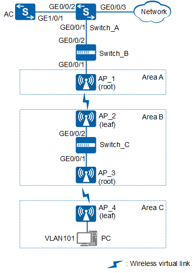
An enterprise has three areas: Area A, Area B, and Area C. In the office environment, AP_1 in Area A can be connected to the AC through a network cable; AP_2 and AP_3 in Area B can be connected through a cable but cannot be connected to the AC in wired mode; Area C is near Area B but AP_4 in Area C cannot be connected to the AC through a network cable either. The enterprise requires that APs be connected to each other in back-to-back WDS mode and go online on the AC to provide network services for PCs in VLAN 101, as shown in Figure 1:
Data Planning
Before configuring the WDS service, determine the types and MAC addresses of the APs used as WDS bridges. The following table provides the data plan for this example.
The APs used in this example are AP6010DN-AGN.
AP |
Type |
MAC |
|---|---|---|
AP_1 |
AP6010DN-AGN |
60de-4474-9640 |
AP_2 |
AP6010DN-AGN |
dcd2-fc04-b500 |
AP_3 |
AP6010DN-AGN |
dcd2-fcf6-76a0 |
AP_4 |
AP6010DN-AGN |
60de-4476-e360 |
The following provides data planning for mesh service configuration.
Item |
Data |
|---|---|
VLAN |
Management VLAN: VLAN 100 |
Service VLAN: VLAN 101 |
|
IP address of the AC's source interface |
VLANIF 100: 10.23.100.1/24 |
WDS profile |
|
WDS role |
|
WDS name |
wds-net |
WDS whitelist |
|
Radio used by WDS |
Radio 1 (AP_1 and AP_2):
Radio 1 (AP_3 and AP_4):
|
Security profile |
|
AP group |
|
Configuration Roadmap
The configuration roadmap is as follows:
- Configure WDS links in Area A and Area B so that AP_1 and AP_2 can go online on the AC.
- Configure Switch_C to enable AP_2 and AP_3 to communicate through the wired network.
- Configure WDS links in Area B and Area C so that AP_4 can go online on the AC.
Procedure
- Configure the AC to communicate with AP_1 and AP_2 to communicate with AP_3.
# Configure access switch Switch_B. Add GE0/0/1 of Switch_B to VLAN 100 (management VLAN) and set the PVID of the interface to VLAN 100. Configure GE0/0/1 and GE0/0/2 to allow packets from VLAN 100 and VLAN 101 to pass through.
<HUAWEI> system-view
[HUAWEI] sysname Switch_B
[Switch_B] vlan batch 100 to 101
[Switch_B] interface gigabitEthernet 0/0/1
[Switch_B-GigabitEthernet0/0/1] port link-type trunk
[Switch_B-GigabitEthernet0/0/1] port trunk pvid vlan 100
[Switch_B-GigabitEthernet0/0/1] port trunk allow-pass vlan 100 to 101
[Switch_B-GigabitEthernet0/0/1] undo port trunk allow-pass vlan 1
[Switch_B-GigabitEthernet0/0/1] stp edged-port enable
[Switch_B-GigabitEthernet0/0/1] port-isolate enable
[Switch_B-GigabitEthernet0/0/1] quit
[Switch_B] interface gigabitEthernet 0/0/2
[Switch_B-GigabitEthernet0/0/2] port link-type trunk
[Switch_B-GigabitEthernet0/0/2] undo port trunk allow-pass vlan 1
[Switch_B-GigabitEthernet0/0/2] port trunk allow-pass vlan 100 to 101
[Switch_B-GigabitEthernet0/0/2] quit
# Configure aggregation switch Switch_A. Configure GE0/0/1 to allow packets from VLAN 100 and VLAN 101 to pass through, GE0/0/2 to allow packets from VLAN 100 to pass through, and GE0/0/3 to allow packets from VLAN 101 to pass through.
<HUAWEI> system-view
[HUAWEI] sysname Switch_A
[Switch_A] vlan batch 100 to 101
[Switch_A] interface gigabitEthernet 0/0/1
[Switch_A-GigabitEthernet0/0/1] port link-type trunk
[Switch_A-GigabitEthernet0/0/1] port trunk allow-pass vlan 100 to 101
[Switch_A-GigabitEthernet0/0/1] undo port trunk allow-pass vlan 1
[Switch_A-GigabitEthernet0/0/1] quit
[Switch_A] interface gigabitEthernet 0/0/2
[Switch_A-GigabitEthernet0/0/2] port link-type trunk
[Switch_A-GigabitEthernet0/0/2] port trunk allow-pass vlan 100
[Switch_A-GigabitEthernet0/0/2] undo port trunk allow-pass vlan 1
[Switch_A-GigabitEthernet0/0/2] quit
[Switch_A] interface gigabitEthernet 0/0/3
[Switch_A-GigabitEthernet0/0/3] port link-type trunk
[Switch_A-GigabitEthernet0/0/3] port trunk allow-pass vlan 101
[Switch_A-GigabitEthernet0/0/3] undo port trunk allow-pass vlan 1
[Switch_A-GigabitEthernet0/0/3] quit
# Configure GE1/0/1 of the AC to allow packets from VLAN 100 to pass through.
<HUAWEI> system-view
[HUAWEI] sysname AC
[AC] vlan batch 100 to 101
[AC] interface gigabitEthernet 1/0/1
[AC-GigabitEthernet1/0/1] port link-type trunk
[AC-GigabitEthernet1/0/1] port trunk allow-pass vlan 100
[AC-GigabitEthernet1/0/1] undo port trunk allow-pass vlan 1
[AC-GigabitEthernet1/0/1] quit
# Configure access switch Switch_C. Configure GE0/0/1 and GE0/0/2 to allow packets from the service and management VLANs to pass through.
<HUAWEI> system-view
[HUAWEI] sysname Switch_C
[Switch_C] vlan batch 100 to 101
[Switch_C] interface gigabitEthernet 0/0/1
[Switch_C-GigabitEthernet0/0/1] port link-type trunk
[Switch_C-GigabitEthernet0/0/1] port trunk allow-pass vlan 100 to 101
[Switch_C-GigabitEthernet0/0/1] undo port trunk allow-pass vlan 1
[Switch_C-GigabitEthernet0/0/1] stp edged-port enable
[Switch_C-GigabitEthernet0/0/1] port-isolate enable
[Switch_C-GigabitEthernet0/0/1] quit
[Switch_C] interface gigabitEthernet 0/0/2
[Switch_C-GigabitEthernet0/0/2] port link-type trunk
[Switch_C-GigabitEthernet0/0/2] port trunk allow-pass vlan 100 to 101
[Switch_C-GigabitEthernet0/0/2] undo port trunk allow-pass vlan 1
[Switch_C-GigabitEthernet0/0/2] quit
- Configure Switch_A to assign IP addresses to PCs and the AC to assign IP addresses to APs.
# Configure Switch_A as a DHCP server to assign IP addresses to PCs from an interface address pool.
Configure the DNS server as required. The common methods are as follows:- In interface address pool scenarios, run the dhcp server dns-list ip-address &<1-8> command in the VLANIF interface view.
- In global address pool scenarios, run the dns-list ip-address &<1-8> command in the IP address pool view.
[Switch_A] dhcp enable
[Switch_A] interface vlanif 101
[Switch_A-Vlanif101] ip address 10.23.101.1 24
[Switch_A-Vlanif101] dhcp select interface
[Switch_A-Vlanif101] quit
# Enable the DHCP function on the AC to allow it to assign IP addresses to APs from an interface address pool.
[AC] dhcp enable
[AC] interface vlanif 100
[AC-Vlanif100] ip address 10.23.100.1 24
[AC-Vlanif100] dhcp select interface
[AC-Vlanif100] quit
- Configure the AP groups, country code, and AC's source interface.
# Create AP group wds-root1 and AP group wds-root2 for root APs and AP group wds-leaf1 and AP group wds-leaf2 for leaf APs.
[AC] wlan
[AC-wlan-view] ap-group name wds-root1
[AC-wlan-ap-group-wds-root1] quit
[AC-wlan-view] ap-group name wds-root2
[AC-wlan-ap-group-wds-root2] quit
[AC-wlan-view] ap-group name wds-leaf1
[AC-wlan-ap-group-wds-leaf1] quit
[AC-wlan-view] ap-group name wds-leaf2
[AC-wlan-ap-group-wds-leaf2] quit
# Create a regulatory domain profile, configure the AC country code in the profile, and apply the profile to the AP groups.
[AC-wlan-view] regulatory-domain-profile name domain1
[AC-wlan-regulate-domain-domain1] country-code cn
[AC-wlan-regulate-domain-domain1] quit
[AC-wlan-view] ap-group name wds-root1
[AC-wlan-ap-group-wds-root1] regulatory-domain-profile domain1
Warning: Modifying the country code will clear channel, power and antenna gain configurations of the radio and reset the AP. Continue?[Y/N]:y
[AC-wlan-ap-group-wds-root1] quit
[AC-wlan-view] ap-group name wds-root2
[AC-wlan-ap-group-wds-root2] regulatory-domain-profile domain1
Warning: Modifying the country code will clear channel, power and antenna gain configurations of the radio and reset the AP. Continue?[Y/N]:y
[AC-wlan-ap-group-wds-root2] quit
[AC-wlan-view] ap-group name wds-leaf1
[AC-wlan-ap-group-wds-leaf1] regulatory-domain-profile domain1
Warning: Modifying the country code will clear channel, power and antenna gain configurations of the radio and reset the AP. Continue?[Y/N]:y
[AC-wlan-ap-group-wds-leaf1] quit
[AC-wlan-view] ap-group name wds-leaf2
[AC-wlan-ap-group-wds-leaf2] regulatory-domain-profile domain1
Warning: Modifying the country code will clear channel, power and antenna gain configurations of the radio and reset the AP. Continue?[Y/N]:y
[AC-wlan-ap-group-wds-leaf2] quit
[AC-wlan-view] quit
# Configure the AC's source interface.
[AC] capwap source interface vlanif 100
# Add AP_1 to AP group wds-root1, AP_3 to AP group wds-root2, AP_2 to AP group wds-leaf1, and AP_4 to AP group wds-leaf2. The default AP authentication mode is MAC address authentication. If the default settings are retained, you do not need to run the ap auth-mode mac-auth command.
In this example, the AP6010DN-AGN is used and has two radios: radio 0 and radio 1.
[AC] wlan
[AC-wlan-view] ap auth-mode mac-auth
[AC-wlan-view] ap-id 1 ap-mac 60de-4474-9640
[AC-wlan-ap-1] ap-name AP_1
[AC-wlan-ap-1] ap-group wds-root1
Warning: This operation may cause AP reset. If the country code changes, it will clear channel, power and antenna gain configuration s of the radio, Whether to continue? [Y/N]:y
[AC-wlan-ap-1] quit
[AC-wlan-view] ap-id 2 ap-mac dcd2-fc04-b500
[AC-wlan-ap-2] ap-name AP_2
[AC-wlan-ap-2] ap-group wds-leaf1
Warning: This operation may cause AP reset. If the country code changes, it will clear channel, power and antenna gain configuration s of the radio, Whether to continue? [Y/N]:y
[AC-wlan-ap-2] quit
[AC-wlan-view] ap-id 3 ap-mac dcd2-fcf6-76a0
[AC-wlan-ap-3] ap-name AP_3
[AC-wlan-ap-3] ap-group wds-root2
Warning: This operation may cause AP reset. If the country code changes, it will clear channel, power and antenna gain configuration s of the radio, Whether to continue? [Y/N]:y
[AC-wlan-ap-3] quit
[AC-wlan-view] ap-id 4 ap-mac 60de-4476-e360
[AC-wlan-ap-4] ap-name AP_4
[AC-wlan-ap-4] ap-group wds-leaf2
Warning: This operation may cause AP reset. If the country code changes, it will clear channel, power and antenna gain configuration s of the radio, Whether to continue? [Y/N]:y
[AC-wlan-ap-4] quit
- Configure WDS service parameters.
# Configure radio parameters for WDS nodes. This example uses radio 1 of the AP6010DN-AGN. coverage distance is the radio coverage distance parameter, which is 3 (unit: 100 m) by default. In this example, the radio coverage distance is set to 4. You can configure the parameter as required.
[AC-wlan-view] ap-group name wds-root1
[AC-wlan-ap-group-wds-root1] radio 1
[AC-wlan-group-radio-wds-root1/1] channel 40mhz-plus 157     //Configure the channel and bandwidth for WDS links. All WDS links on the same WDS network must be configured with the same channel and bandwidth.
[AC-wlan-group-radio-wds-root1/1] coverage distance 4     //After the radio coverage distance parameter is configured based on distances between APs, the APs will automatically adjust the values of slottime, acktimeout, and ctstimeout based on the configured distance parameter.
[AC-wlan-group-radio-wds-root1/1] quit
[AC-wlan-ap-group-wds-root1] quit
[AC-wlan-view] ap-group name wds-root2
[AC-wlan-ap-group-wds-root2] radio 1
[AC-wlan-group-radio-wds-root2/1] channel 40mhz-plus 149
[AC-wlan-group-radio-wds-root2/1] coverage distance 4
[AC-wlan-group-radio-wds-root2/1] quit
[AC-wlan-ap-group-wds-root2] quit
[AC-wlan-view] ap-group name wds-leaf1
[AC-wlan-ap-group-wds-leaf1] radio 1
[AC-wlan-group-radio-wds-leaf1/1] channel 40mhz-plus 157
[AC-wlan-group-radio-wds-leaf1/1] coverage distance 4
[AC-wlan-group-radio-wds-leaf1/1] quit
[AC-wlan-ap-group-wds-leaf1] quit
[AC-wlan-view] ap-group name wds-leaf2
[AC-wlan-ap-group-wds-leaf2] radio 1
[AC-wlan-group-radio-wds-leaf2/1] channel 40mhz-plus 149
[AC-wlan-group-radio-wds-leaf2/1] coverage distance 4
[AC-wlan-group-radio-wds-leaf2/1] quit
[AC-wlan-ap-group-wds-leaf2] quit
# Configure the security profile wds-sec used by WDS links. The wds-sec uses the security policy WPA2+PSK+AES.
[AC-wlan-view] security-profile name wds-sec
[AC-wlan-sec-prof-wds-sec] security wpa2 psk pass-phrase a1234567 aes
[AC-wlan-sec-prof-wds-sec] quit
# Configure a WDS whitelist. Configure the WDS whitelist wds-list1 bound to AP_1 to permit access only from AP_2 and the WDS whitelist wds-list2 bound to AP_3 to permit access only from AP_4.
[AC-wlan-view] wds-whitelist-profile name wds-list1
[AC-wlan-wds-whitelist-wds-list1] peer-ap mac dcd2-fc04-b500
[AC-wlan-wds-whitelist-wds-list1] quit
[AC-wlan-view] wds-whitelist-profile name wds-list2
[AC-wlan-wds-whitelist-wds-list2] peer-ap mac 60de-4476-e360
[AC-wlan-wds-whitelist-wds-list2] quit
# Configure the WDS profile wds-net1. Set the WDS name to wds-net and WDS mode to root. Apply the security profile wds-sec and allow packets from service VLAN 101 to pass through in tagged mode.
[AC-wlan-view] wds-profile name wds-net1
[AC-wlan-wds-prof-wds-net1] wds-name wds-net     //Only WDS VAPs with the same WDS name can set up WDS links.
[AC-wlan-wds-prof-wds-net1] wds-mode root
[AC-wlan-wds-prof-wds-net1] security-profile wds-sec
[AC-wlan-wds-prof-wds-net1] vlan tagged 101
[AC-wlan-wds-prof-wds-net1] quit
# Configure the WDS profile wds-net2. Set the WDS name to wds-net and WDS mode to root. Apply the security profile wds-sec and allow packets from service VLAN 101 to pass through in tagged mode.
[AC-wlan-view] wds-profile name wds-net2
[AC-wlan-wds-prof-wds-net2] wds-name wds-net
[AC-wlan-wds-prof-wds-net2] wds-mode root
[AC-wlan-wds-prof-wds-net2] security-profile wds-sec
[AC-wlan-wds-prof-wds-net2] vlan tagged 101
[AC-wlan-wds-prof-wds-net2] quit
# Configure the WDS profile wds-net3. Set the WDS name to wds-net and WDS mode to leaf. Bind the security profile wds-sec to the WDS profile, allowing packets from service VLAN 101 to pass through in tagged mode.
[AC-wlan-view] wds-profile name wds-net3
[AC-wlan-wds-prof-wds-net3] wds-name wds-net
[AC-wlan-wds-prof-wds-net3] wds-mode leaf
[AC-wlan-wds-prof-wds-net3] security-profile wds-sec
[AC-wlan-wds-prof-wds-net3] vlan tagged 101
[AC-wlan-wds-prof-wds-net3] quit
# Bind the WDS whitelist wds-list1 to radio 1 in AP group wds-root1 to permit access only from AP_2. Bind the WDS whitelist wds-list2 to radio 1 in AP group wds-root2 to permit access only from AP_4.
[AC-wlan-view] ap-group name wds-root1
[AC-wlan-ap-group-wds-root1] radio 1
[AC-wlan-group-radio-wds-root1/1] wds-whitelist-profile wds-list1
[AC-wlan-group-radio-wds-root1/1] quit
[AC-wlan-ap-group-wds-root1] quit
[AC-wlan-view] ap-group name wds-root2
[AC-wlan-ap-group-wds-root2] radio 1
[AC-wlan-group-radio-wds-root2/1] wds-whitelist-profile wds-list2
[AC-wlan-group-radio-wds-root2/1] quit
[AC-wlan-ap-group-wds-root2] quit
- Configure the wired port profile used by the wired interface of AP_4 and set the wired interface mode to endpoint. In this example, the PVID of the wired interface is set to VLAN 101 and the wired interface is added to VLAN 101 in untagged mode.
[AC-wlan-view] wired-port-profile name wired-port
[AC-wlan-wired-port-wired-port] mode endpoint
[AC-wlan-wired-port-wired-port] vlan pvid 101
[AC-wlan-wired-port-wired-port] vlan untagged 101
[AC-wlan-wired-port-wired-port] quit
- Bind required profiles to the AP groups to make WDS services take effect.
# Configure the AP group wds-root1 and bind the WDS profile wds-net1 to the group.
[AC-wlan-view] ap-group name wds-root1
[AC-wlan-ap-group-wds-root1] wds-profile wds-net1 radio 1
[AC-wlan-ap-group-wds-root1] quit
# Configure the AP group wds-root2 and bind the WDS profile wds-net2 to the group.
[AC-wlan-view] ap-group name wds-root2
[AC-wlan-ap-group-wds-root2] wds-profile wds-net2 radio 1
[AC-wlan-ap-group-wds-root2] quit
# Configure the AP group wds-leaf1 and bind the WDS profile wds-net3 to the group.
[AC-wlan-view] ap-group name wds-leaf1
[AC-wlan-ap-group-wds-leaf1] wds-profile wds-net3 radio 1
[AC-wlan-ap-group-wds-leaf1] quit
# Configure the AP group wds-leaf2, and bind the WDS profile wds-net3 and wired port profile wired-port to the group.
[AC-wlan-view] ap-group name wds-leaf2
[AC-wlan-ap-group-wds-leaf2] wds-profile wds-net3 radio 1
[AC-wlan-ap-group-wds-leaf2] wired-port-profile wired-port gigabitethernet 0
[AC-wlan-ap-group-wds-leaf2] quit
- Commit the configuration.
[AC-wlan-view] commit all
Warning: Committing configuration may cause service interruption, continue?[Y/N]:y
- Verify the WDS service configuration.
# After the configuration is complete, run the display ap all command to check whether WDS nodes go online successfully. If State is nor, the APs have gone online.
[AC-wlan-view] display ap all
Total AP information:
nor  : normal          [4]
--------------------------------------------------------------------------------
------
ID   MAC            Name Group     IP              Type            State STA Upt
ime
--------------------------------------------------------------------------------
------
1    60de-4474-9640 AP_1 wds-root1 10.23.100.250   AP6010DN-AGN    nor   0
  20M:16S
4    60de-4476-e360 AP_4 wds-leaf2 10.23.100.251   AP6010DN-AGN    nor   0
  17S
2    dcd2-fc04-b500 AP_2 wds-leaf1 10.23.100.253   AP6010DN-AGN    nor   0
  3M:55S
3    dcd2-fcf6-76a0 AP_3 wds-root2 10.23.100.252   AP6010DN-AGN    nor   0
  2M:55S
--------------------------------------------------------------------------------
----
Total: 4
Run the display wlan wds link all command to check information about the WDS links.
[AC-wlan-view] display wlan wds link all
Rf   : radio ID             Dis  : coverage distance(100m)
Ch   : channel              Per  : drop percent(%)
TSNR : total SNR(dB)        P-   : peer
WDS  : WDS mode             Re   : retry ratio(%)
RSSI : RSSI(dBm)            MaxR : max RSSI(dBm)
--------------------------------------------------------------------------------
-----------------
APName  P-APName  Rf Dis   Ch   WDS     P-Status        RSSI  MaxR  Per  Re   TS
NR  SNR(Ch0~2:dB)
--------------------------------------------------------------------------------
-----------------
AP_1    AP_2      1  3     157  root    normal          -44   -40   0    3    50
   45/49/-
AP_2    AP_1      1  3     157  leaf    normal          -38   -36   0    49   57
   36/31/57
AP_3    AP_4      1  3     149  root    normal          -11   -7    0    1    83
   81/80/-
AP_4    AP_3      1  3     149  leaf    normal          -4    -4    0    0    91
   90/85/-
--------------------------------------------------------------------------------
-----------------
Total: 4
Configuration Files
Switch_A configuration file
#
sysname Switch_A
#
 vlan batch 100 to 101
#
dhcp enable
#
interface Vlanif101
 ip address 10.23.101.1 255.255.255.0
 dhcp select interface
#
interface GigabitEthernet0/0/1
 port link-type trunk
 undo port trunk allow-pass vlan 1
 port trunk allow-pass vlan 100 to 101
#
interface GigabitEthernet0/0/2
 port link-type trunk
 undo port trunk allow-pass vlan 1
 port trunk allow-pass vlan 100
#
interface GigabitEthernet0/0/3
 port link-type trunk
 undo port trunk allow-pass vlan 1
 port trunk allow-pass vlan 101
#
return
Switch_B configuration file
#
sysname Switch_B
#
 vlan batch 100 to 101
#
interface GigabitEthernet0/0/1
 port link-type trunk
 port trunk pvid vlan 100
 undo port trunk allow-pass vlan 1
 port trunk allow-pass vlan 100 to 101
 stp edged-port enable
 port-isolate enable group 1
#
interface GigabitEthernet0/0/2
 port link-type trunk
 undo port trunk allow-pass vlan 1
 port trunk allow-pass vlan 100 to 101
#
return
Switch_C configuration file
#
sysname Switch_C
#
 vlan batch 100 to 101
#
interface GigabitEthernet0/0/1
 port link-type trunk
 undo port trunk allow-pass vlan 1
 port trunk allow-pass vlan 100 to 101
 stp edged-port enable
 port-isolate enable group 1
#
interface GigabitEthernet0/0/2
 port link-type trunk
 undo port trunk allow-pass vlan 1
 port trunk allow-pass vlan 100 to 101
#
return
AC configuration file
#
 sysname AC
#
 vlan batch 100 to 101
#
dhcp enable
#
interface Vlanif100
 ip address 10.23.100.1 255.255.255.0
 dhcp select interface
#
interface GigabitEthernet1/0/1
 port link-type trunk
 undo port trunk allow-pass vlan 1
 port trunk allow-pass vlan 100
#
capwap source interface vlanif100
#
wlan
 security-profile name wds-sec
  security wpa2 psk pass-phrase %^%#n}5+DgC3wLB.hJ34j5;*QMv<8"9#{Bq@ghBI3L9K%^%# aes
 wds-whitelist-profile name wds-list1
  peer-ap mac dcd2-fc04-b500
 wds-whitelist-profile name wds-list2
  peer-ap mac 60de-4476-e360
 wds-profile name wds-net1
  security-profile wds-sec
  vlan tagged 101
  wds-name wds-net
  wds-mode root
 wds-profile name wds-net2
  security-profile wds-sec
  vlan tagged 101
  wds-name wds-net
  wds-mode root
 wds-profile name wds-net3
  security-profile wds-sec
  vlan tagged 101
  wds-name wds-net
 regulatory-domain-profile name domain1
 wired-port-profile name wired-port
  mode endpoint
  vlan pvid 101
  vlan untagged 101
 ap-group name wds-leaf1
  regulatory-domain-profile domain1
  radio 1
   wds-profile wds-net3
   channel 40mhz-plus 157
   coverage distance 4
 ap-group name wds-leaf2
  wired-port-profile wired-port gigabitethernet 0
  regulatory-domain-profile domain1
  radio 1
   wds-profile wds-net3
   channel 40mhz-plus 149
   coverage distance 4
 ap-group name wds-root1
  regulatory-domain-profile domain1
  radio 1
   wds-profile wds-net1
   wds-whitelist-profile wds-list1
   channel 40mhz-plus 157
   coverage distance 4
 ap-group name wds-root2
  regulatory-domain-profile domain1
  radio 1
   wds-profile wds-net2
   wds-whitelist-profile wds-list2
   channel 40mhz-plus 149
   coverage distance 4
 ap-id 1 type-id 19 ap-mac 60de-4474-9640 ap-sn 210235554710CB000042
  ap-name AP_1
  ap-group wds-root1
 ap-id 2 type-id 19 ap-mac dcd2-fc04-b500 ap-sn 210235555310CC000094
  ap-name AP_2
  ap-group wds-leaf1
 ap-id 3 type-id 19 ap-mac dcd2-fcf6-76a0 ap-sn 210235419610D2000097
  ap-name AP_3
  ap-group wds-root2
 ap-id 4 type-id 19 ap-mac 60de-4476-e360 ap-sn 210235557610DB000046
  ap-name AP_4
  ap-group wds-leaf2
#
return