Example for configuring VXLAN to Enable Communication for Users in the Same Network Segment (Static Mode)
Networking Requirements
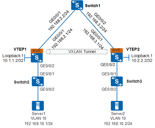
- Servers scattered in different departments form a virtual network, realizing resource integration and flexible service deployment.
- A large number of VMs are deployed on each server, and VMs providing the same service can communicate at Layer 2.
- VMs can be smoothly migrated between servers based on service requirements, ensuring service continuity.

This example uses the S6730-S, S6730S-S, S5732-H, S5731-S, S5731S-S, S5731S-H, S6730-H, S6730S-H, S5731-H, S5720-HI, S5730-HI, or S6720-HI as an example to describe the configuration.
Data Plan
Device |
VXLAN Tunnel |
BD |
VNI |
Source IP |
Peer IP |
|---|---|---|---|---|---|
VTEP1 |
VTEP1—>VTEP2 |
10 |
2010 |
10.1.1.2 |
10.2.2.2 |
VTEP2 |
VTEP2—>VTEP1 |
10 |
2010 |
10.2.2.2 |
10.1.1.2 |
Configuration Roadmap
The configuration roadmap is as follows:
- Configure a routing protocol on VTEP1, VTEP2, and Switch1 to ensure Layer 3 network connectivity.
- Configure a deployment mode for the VXLAN access service on VTEP1 and VTEP2, and configure a VLAN on Switch2 and Switch3.
- Configure information for VXLAN tunnel establishment on VTEP1 and VTEP2.
Layer 3 interconnection of the campus network is the basis of the virtual network. If Layer 3 interconnection has been implemented on the live campus network, step 1 in this example can be omitted.
Procedure
- Configure a routing protocol.
# Assign IP addresses to the interfaces of VTEP1. The configurations of VTEP2 and Switch1 are similar to the configuration of VTEP1, and are not mentioned here. When OSPF is used, the loopback address of each switch must be advertised.
<HUAWEI> system-view
[HUAWEI] sysname VTEP1
[VTEP1] interface loopback 1
[VTEP1-LoopBack1] ip address 10.1.1.2 32
[VTEP1-LoopBack1] quit
[VTEP1] interface gigabitethernet 0/0/1
[VTEP1-GigabitEthernet0/0/1] undo portswitch
[VTEP1-GigabitEthernet0/0/1] ip address 192.168.2.1 24
[VTEP1-GigabitEthernet0/0/1] quit
[VTEP1] ospf router-id 10.1.1.2
[VTEP1-ospf-1] area 0
[VTEP1-ospf-1-area-0.0.0.0] network 10.1.1.2 0.0.0.0
[VTEP1-ospf-1-area-0.0.0.0] network 192.168.2.0 0.0.0.255
[VTEP1-ospf-1-area-0.0.0.0] quit
[VTEP1-ospf-1] quit
# After OSPF is configured, the switches can learn the loopback interface address of each other and successfully ping each other. The following shows the ping result from VTEP1 to VTEP2.
[VTEP1] ping 10.2.2.2 PING 10.2.2.2: 56 data bytes, press CTRL_C to break Reply from 10.2.2.2: bytes=56 Sequence=1 ttl=255 time=240 ms Reply from 10.2.2.2: bytes=56 Sequence=2 ttl=255 time=5 ms Reply from 10.2.2.2: bytes=56 Sequence=3 ttl=255 time=5 ms Reply from 10.2.2.2: bytes=56 Sequence=4 ttl=255 time=14 ms Reply from 10.2.2.2: bytes=56 Sequence=5 ttl=255 time=5 ms --- 10.2.2.2 ping statistics --- 5 packet(s) transmitted 5 packet(s) received 0.00% packet loss round-trip min/avg/max = 5/53/240 ms - Configure VLAN access on Switch2 and Switch3 and configure the access point for the VXLAN service on VTEP1 and VTEP2.
# Configure Switch2.
<HUAWEI> system-view
[HUAWEI] sysname Switch2
[Switch2] vlan 10
[Switch2-vlan10] quit
[Switch2] interface gigabitethernet 0/0/2
[Switch2-GigabitEthernet0/0/2] port link-type access
[Switch2-GigabitEthernet0/0/2] port default vlan 10
[Switch2-GigabitEthernet0/0/2] quit
[Switch2] interface gigabitethernet 0/0/1
[Switch2-GigabitEthernet0/0/1] port link-type trunk
[Switch2-GigabitEthernet0/0/1] port trunk allow-pass vlan 10
[Switch2-GigabitEthernet0/0/1] quit
# Configure Switch3.
<HUAWEI> system-view
[HUAWEI] sysname Switch3
[Switch3] vlan 10
[Switch3-vlan10] quit
[Switch3] interface gigabitethernet 0/0/2
[Switch3-GigabitEthernet0/0/2] port link-type access
[Switch3-GigabitEthernet0/0/2] port default vlan 10
[Switch3-GigabitEthernet0/0/2] quit
[Switch3] interface gigabitethernet 0/0/1
[Switch3-GigabitEthernet0/0/1] port link-type trunk
[Switch3-GigabitEthernet0/0/1] port trunk allow-pass vlan 10
[Switch3-GigabitEthernet0/0/1] quit
# Configure VTEP1.
[VTEP1] bridge-domain 10
[VTEP1-bd10] quit
[VTEP1] vcmp role silent
[VTEP1] interface gigabitethernet 0/0/2
[VTEP1-GigabitEthernet0/0/2] port link-type trunk
[VTEP1-GigabitEthernet0/0/2] quit
[VTEP1] interface gigabitethernet 0/0/2.1 mode l2
[VTEP1-GigabitEthernet0/0/2.1] encapsulation dot1q vid 10
[VTEP1-GigabitEthernet0/0/2.1] bridge-domain 10
[VTEP1-GigabitEthernet0/0/2.1] quit
# Configure VTEP2.
[VTEP2] bridge-domain 10
[VTEP2-bd10] quit
[VTEP2] vcmp role silent
[VTEP2] interface gigabitethernet 0/0/2
[VTEP2-GigabitEthernet0/0/2] port link-type trunk
[VTEP2-GigabitEthernet0/0/2] quit
[VTEP2] interface gigabitethernet 0/0/2.1 mode l2
[VTEP2-GigabitEthernet0/0/2.1] encapsulation dot1q vid 10
[VTEP2-GigabitEthernet0/0/2.1] bridge-domain 10
[VTEP2-GigabitEthernet0/0/2.1] quit
- Configure information for VXLAN tunnel establishment on VTEP1 and VTEP2.
# Configure VTEP1.
[VTEP1] bridge-domain 10
[VTEP1-bd10] vxlan vni 2010
[VTEP1-bd10] quit
[VTEP1] interface nve 1
[VTEP1-Nve1] source 10.1.1.2
[VTEP1-Nve1] vni 2010 head-end peer-list 10.2.2.2
[VTEP1-Nve1] quit
# Configure VTEP2.
[VTEP2] bridge-domain 10
[VTEP2-bd10] vxlan vni 2010
[VTEP2-bd10] quit
[VTEP2] interface nve 1
[VTEP2-Nve1] source 10.2.2.2
[VTEP2-Nve1] vni 2010 head-end peer-list 10.1.1.2
[VTEP2-Nve1] quit
- Verify the configuration.
# After the preceding configuration, run the display vxlan vni and display vxlan tunnel commands on VTEP1 and VTEP2. You can view that the VNI status is up and VXLAN tunnel information is displayed. The command output of VTEP1 is used as an example.
[VTEP1] display vxlan vni
 VNI               BD-ID             State
 -----------------------------------------
 2010              10                up
 -----------------------------------------
 Number of vxlan vni bound to BD is : 1

 VNI               VRF-ID
 -----------------------------------------
 -----------------------------------------
 Number of vxlan vni bound to VPN is : 0
[VTEP1] display vxlan tunnel
 Tunnel ID       Source              Destination         State     Type
 ----------------------------------------------------------------------------
 4026531841      10.1.1.2             10.2.2.2             up        static
----------------------------------------------------------------------------
 Number of vxlan tunnel :
 Total : 1    Static: 1    L2 dynamic: 0    L3 dynamic: 0
# After the configuration is complete, users in the same network segment can communicate over a VXLAN tunnel. The following shows the ping result from VM1 on Server1 to VM1 on Server2.
C:\Users\VM1>ping 192.168.10.2

Pinging 192.168.10.2 with 32 bytes of data:
Reply from 192.168.10.2: bytes=32 time=1ms TTL=126
Reply from 192.168.10.2: bytes=32 time=1ms TTL=126
Reply from 192.168.10.2: bytes=32 time=1ms TTL=126
Reply from 192.168.10.2: bytes=32 time=1ms TTL=126

Ping statistics for 192.168.10.2:
    Packets: Sent = 4, Received = 4, Lost = 0 (0% loss),
Approximate round trip times in milli-seconds:
    Minimum = 1ms, Maximum = 1ms, Average = 1ms
Configuration Files
VTEP1 configuration file
#
sysname VTEP1
#
vcmp role silent
#
bridge-domain 10
 vxlan vni 2010
#
interface GigabitEthernet0/0/1
 undo portswitch
 ip address 192.168.2.1 255.255.255.0
#
interface GigabitEthernet0/0/2
 port link-type trunk
#
interface GigabitEthernet0/0/2.1 mode l2
 encapsulation dot1q vid 10
 bridge-domain 10
#
interface LoopBack1
 ip address 10.1.1.2 255.255.255.255
#
interface Nve1
 source 10.1.1.2
 vni 2010 head-end peer-list 10.2.2.2
#
ospf 1 router-id 10.1.1.2
 area 0.0.0.0
  network 10.1.1.2 0.0.0.0
  network 192.168.2.0 0.0.0.255
#
return
VTEP2 configuration file
#
sysname VTEP2
#
vcmp role silent
#
bridge-domain 10
 vxlan vni 2010
#
interface GigabitEthernet0/0/1
 undo portswitch
 ip address 192.168.3.1 255.255.255.0
#
interface GigabitEthernet0/0/2
 port link-type trunk
#
interface GigabitEthernet0/0/2.1 mode l2
 encapsulation dot1q vid 10
 bridge-domain 10
#
interface LoopBack1
 ip address 10.2.2.2 255.255.255.255
#
interface Nve1
 source 10.2.2.2
 vni 2010 head-end peer-list 10.1.1.2
#
ospf 1 router-id 10.2.2.2
 area 0.0.0.0
  network 10.2.2.2 0.0.0.0
  network 192.168.3.0 0.0.0.255
#
return
Switch1 configuration file
#
sysname Switch1
#
interface GigabitEthernet0/0/1
 undo portswitch
 ip address 192.168.2.2 255.255.255.0
#
interface GigabitEthernet0/0/2
 undo portswitch
 ip address 192.168.3.2 255.255.255.0
#
ospf 1 router-id 192.168.2.2
 area 0.0.0.0
  network 192.168.2.0 0.0.0.255
  network 192.168.3.0 0.0.0.255
#
return
Configuration file of Switch2
#
sysname Switch2
#
vlan batch 10
#
interface GigabitEthernet0/0/1
 port link-type trunk
 port trunk allow-pass vlan 10
#
interface GigabitEthernet0/0/2
 port link-type access
 port default vlan 10
#
return
Configuration file of Switch3
#
sysname Switch3
#
vlan batch 10
#
interface GigabitEthernet0/0/1
 port link-type trunk
 port trunk allow-pass vlan 10
#
interface GigabitEthernet0/0/2
 port link-type access
 port default vlan 10
#
return