Applying a Virtual Network in the User Access Authentication Scenario
In Figure 1, an enterprise builds a virtual network on a campus network using VXLAN for network planning. The office zone and guest zone connect to the virtual network through VTEP2 and VTEP3, respectively. Network access of the users needs to be controlled to ensure security of the enterprise intranet. Only the users who pass authentication are allowed to access authorized network resources.
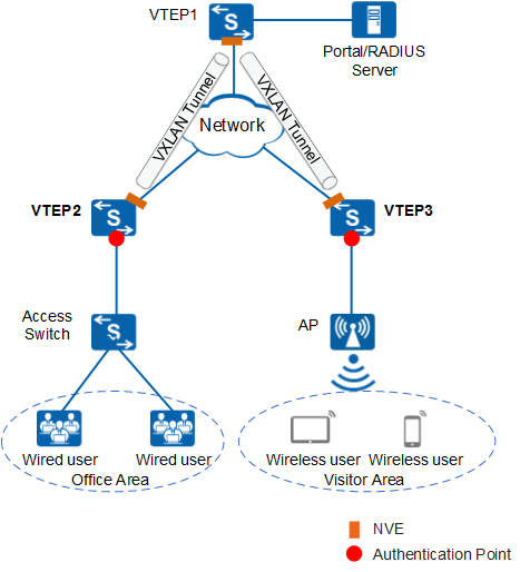
VXLAN-built virtual networks support two user access modes: VLAN and sub-interface. In the given scenario, user access can be authenticated only on physical interfaces. Therefore, in the user authentication scenario on a VXLAN network, user authentication and transparent VLAN transmission can be performed only on physical interfaces. The following describes how a wired user in Figure 1 is authenticated and accesses network resources:
- After the user is connected to the access switch, a VLAN tag is added to the packet.
- Upon arriving at VTEP2, the authentication request packet carrying the VLAN tag is VXLAN-encapsulated and sent to VTEP1 based on the binding relationship between the VLAN and BD on the device.
- VTEP1 decapsulates the received packet and sends it to the Portal or RADIUS server for authentication based on the binding relationship between the VLAN and BD.
- After the authentication is complete, the packet carrying the authentication response enters the VXLAN tunnel through VTEP1 and is then sent to VTEP2.
- VTEP2 decapsulates the packet from VTEP1, obtains the authentication response from the Portal or RADIUS server, and completes user authentication.