Optical Fiber
Active Optical Cable
An active optical cable (AOC) is an optical fiber with optical modules at both ends, making it easy to use. Figure 1, Figure 2, and Figure 3 show the appearance of AOC cables.
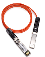
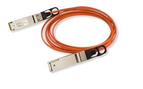
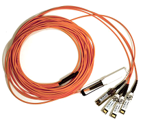
Table 1 lists the models and attributes of AOC cables.
Model |
Length |
Bend Radius |
Connector Type |
Part Number |
Operating Temperature |
|---|---|---|---|---|---|
SFP-10G-AOC3M |
3 m |
30 mm |
SFP+ connectors at both ends |
02310QWG |
0°C to 70°C |
SFP-10G-AOC10M |
10 m |
30 mm |
SFP+ connectors at both ends |
02310QWH |
0°C to 70°C |
QSFP-H40G-AOC10M |
10 m |
25 mm |
QSFP+ connectors at both ends |
02310SSH |
0°C to 70°C |
QSFP-4SFP10-AOC10M |
10 m |
25 mm |
QSFP+ connector at one end and four SFP+ connectors at the other end |
02310SSJ |
0°C to 70°C |
QSFP-100G-AOC-10M |
10 m |
25 mm |
QSFP28 connectors at both ends |
02311KNQ |
0°C to 70°C |
SFP-25G-AOC-3M |
3 m |
30 mm |
SFP28 connectors at both ends |
02311MPE |
0°C to 70°C |
SFP-25G-AOC-5M |
5 m |
30 mm |
SFP28 connectors at both ends |
02311MPD |
0°C to 70°C |
SFP-25G-AOC-7M |
7 m |
30 mm |
SFP28 connectors at both ends |
02311MPC |
0°C to 70°C |
SFP-25G-AOC-10M |
10 m |
30 mm |
SFP28 connectors at both ends |
02311KNT |
0°C to 70°C |
Fiber Jumper
A fiber jumper consists of one or more fibers of a certain length and the optical connectors at both ends. A fiber jumper connects an optical module to a fiber terminal box.

- The MPO-MPO and MPO-2*MPO fibers have similar appearances except for the number of MPO connectors at the other end. The following figures show an MPO-MPO fiber for example.
- The MPO-4*DLC and MPO-10*DLC fibers have similar appearances except for the number of DLC connectors at the other end.
- The MPO-MPO fibers for S series switches use type B connectors (key Up/key Up).
Figure 4 shows a single-mode LC/PC fiber jumper.
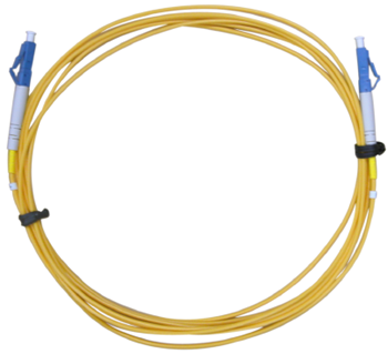
Figure 5 shows a multimode LC/PC fiber jumper.
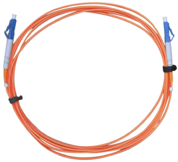
Figure 6 shows a single-mode SC/PC fiber jumper.
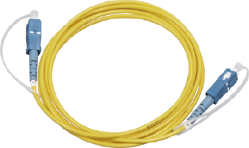
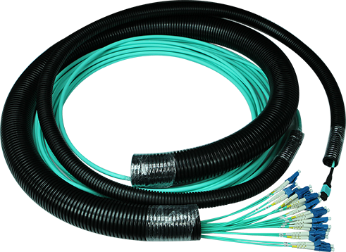
Figure 7 shows an MPO-MPO fiber jumper.
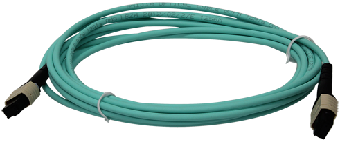
Figure 8 shows an MPO-4*DLC fiber jumper.
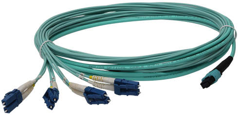
Figure 9 shows an MPO-10*DLC fiber jumper.
- Determine the length of fiber jumpers based on the onsite cabling distance.
- Determine the fiber type based on the optical module type.
- Use a multimode fiber jumper for a multimode optical module.
- Use a single-mode fiber jumper for a single-mode optical module.
Determine the optical connector type based on the interface type.
Ensure that the optical connector at each end of a fiber jumper is the same type as the interface to which it will be connected.
Figure 10 shows the structure of an 8-strand MPO-MPO fiber jumper.
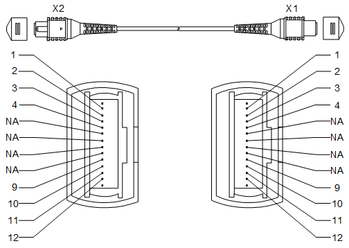
Figure 11 shows the structure of a 12-strand MPO-MPO fiber jumper.
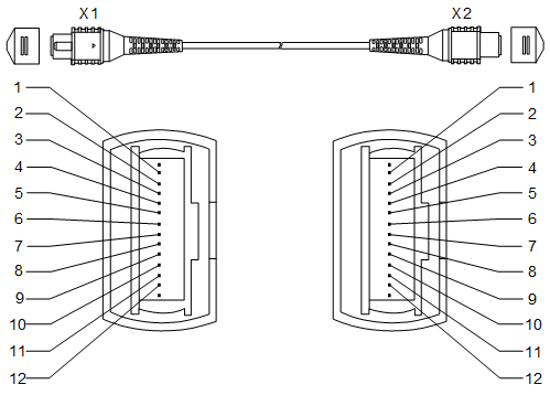
Figure 12 shows the structure of a 24-strand MPO-MPO fiber jumper.

Figure 13 shows the structure of an MPO-4*DLC fiber jumper.
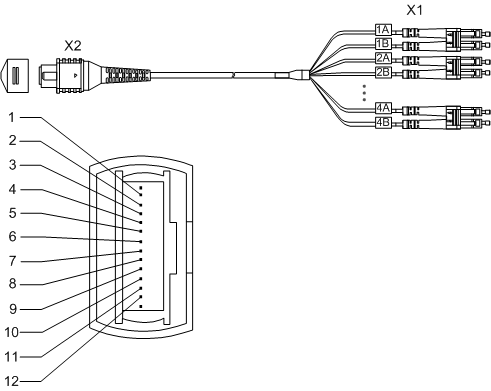
Figure 14 shows the structure of an MPO-2*MPO fiber jumper.
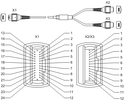
Figure 15 shows the structure of an MPO-10*DLC fiber jumper.

Table 2 lists the pin assignments of an 8-strand MPO-MPO fiber jumper.
X1 Pin |
X2 Pin |
|---|---|
1 |
12 |
2 |
11 |
3 |
10 |
4 |
9 |
NA |
NA |
NA |
NA |
NA |
NA |
NA |
NA |
9 |
4 |
10 |
3 |
11 |
2 |
12 |
1 |
Table 3 lists the pin assignments of a 12-strand MPO-MPO fiber jumper.
X1 Pin |
X2 Pin |
|---|---|
1 |
12 |
2 |
11 |
3 |
10 |
4 |
9 |
5 |
8 |
6 |
7 |
7 |
6 |
8 |
5 |
9 |
4 |
10 |
3 |
11 |
2 |
12 |
1 |
Table 4 lists the pin assignments of a 24-strand MPO-MPO fiber jumper.
X1 Pin |
X2 Pin |
X1 Pin |
X2 Pin |
|---|---|---|---|
1 |
24 |
13 |
12 |
2 |
23 |
14 |
11 |
3 |
22 |
15 |
10 |
4 |
21 |
16 |
9 |
5 |
20 |
17 |
8 |
6 |
19 |
18 |
7 |
7 |
18 |
19 |
6 |
8 |
17 |
20 |
5 |
9 |
16 |
21 |
4 |
10 |
15 |
22 |
3 |
11 |
14 |
23 |
2 |
12 |
13 |
24 |
1 |
Table 5 lists the pin assignments of an MPO-4*DLC fiber jumper.
X2 Pin |
X1 Pin |
|---|---|
1 |
1A |
2 |
2A |
3 |
3A |
4 |
4A |
9 |
4B |
10 |
3B |
11 |
2B |
12 |
1B |
Table 6 lists the pin assignments of an MPO-2*MPO fiber jumper.
X1 Pin |
X2 Pin |
X3 Pin |
|---|---|---|
2 |
12 |
NA |
3 |
11 |
NA |
4 |
10 |
NA |
5 |
9 |
NA |
7 |
NA |
12 |
8 |
NA |
11 |
9 |
NA |
10 |
10 |
NA |
9 |
14 |
1 |
NA |
15 |
2 |
NA |
16 |
3 |
NA |
17 |
4 |
NA |
19 |
NA |
1 |
20 |
NA |
2 |
21 |
NA |
3 |
22 |
NA |
4 |
Table 7 lists the pin assignments of an MPO-10*DLC fiber jumper.
Fiber Pigtail
A fiber pigtail is an optical fiber that has an optical connector on one end and a piece of exposed fiber at the other end. The exposed fiber can be fused to another optical fiber. Fiber pigtails are commonly used to connect optical fibers to optical modules in fiber terminal boxes (couplers and jumpers are also used). Figure 16 shows the structure of a fiber pigtail.
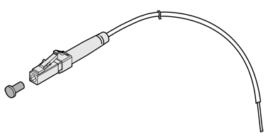
Fiber pigtails are classified into single-mode and multimode fiber pigtails and are used for short-distance connections.
Optical Fiber, Optical Connector, and Fiber Adapter
Optical Fibers
Optical fibers are classified into single-mode fibers and multimode fibers.
Single-mode fibers have a diameter of 5-10 μm and transmit laser in one mode under a specified wavelength. These fibers support a wide frequency band and a large transmission capacity, so they are used for long-distance transmission. Most single-mode fibers are yellow, as shown in Figure 4.
Multimode fibers have a diameter of 50 μm or 62.5 μm and transmit laser light in multiple modes with a specified wavelength. These fibers have a lower transmission capacity than single-mode fibers and are used for short-distance transmission. Model dispersion occurs during transmission over multimode fibers.
In the latest cabling infrastructure of ISO/IEC 11801, multimode fibers are classified into four categories: OM1, OM2, OM3, and OM4.- OM1: traditional 62.5/125 μm multimode fibers. OM1 fibers have a large core diameter and numerical aperture, and provide high light gathering ability and bending resistance.
- OM2: traditional 50/125 μm multimode fibers. OM2 fibers have a small core diameter and numerical aperture. Compared with OM1 fibers, OM2 fibers provide higher bandwidth because they significantly reduce the modal dispersion. When transmitting data at 1 Gbit/s with 850 nm wavelength, OM1 and OM2 fibers support maximum link lengths of 220 m and 550 m, respectively. OM1 and OM2 fibers can provide sufficient bandwidth within a distance of 300 m. Generally, OM1 and OM2 fibers are orange, as shown in Figure 5.
- OM3: new-generation multimode fibers, with longer transmission distances than OM1 and OM2 fibers.
- OM4: laser optimized multimode fibers with 50 μm core diameter. OM4 is an improvement to OM3 and only increases the modal bandwidth. OM4 fibers provide 4700 MHz*km of modal bandwidth, whereas OM3 fibers provide only 2000 MHz*km of modal bandwidth. Generally, OM3 and OM4 fibers are light green, as shown in Figure 7. You can identify OM3 and OM4 fibers by their labels or printed marks.
- A 40G optical module uses four channels to transmit laser and four channels to receive laser. That is, a total of eight channels are required for a 40G optical module. 8-strand and 12-strand MPO fibers use the same definition of fiber channels. Therefore, they are equivalent in functionality when connecting to 40G optical modules.
- When 100G optical modules are used, choose MPO fibers according to the following rules:
- For CFP optical modules, choose 24-strand fibers for the CFP-100G-SR10 module and 8-strand or 12-strand fibers for other modules.
- Choose 8-strand or 12-strand fibers for QSFP28 modules.
Optical Connector
Optical connectors are used to connect optical fibers of the same type. Table 8 lists common optical connectors.
Connector Type |
Optical Connector |
|||
|---|---|---|---|---|
Square connector |
SC/PC connector
|
LC/PC connector
|
MTRJ/PC connector
|
MPO connector
|
Round connector |
FC/PC connector
|
ST/PC connector
|
- |
- |


Figure 17 shows an LC/PC optical connector.
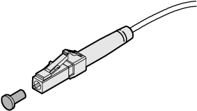

When connecting or removing an LC/PC optical connector, align the connector with the optical port and do not rotate the fiber. Pay attention to the following points:
Fiber Adapter
A fiber adapter (also called a flange) is a fiber connection component. Two fiber connectors need to be connected using a fiber adapter. Fiber adapters are widely used in optical distribution frames (ODFs), fiber transmission equipment, and optical instruments.