3-Pin AC Power Cable (Phoenix Connector)
Appearance and Structure
Figure 1 shows the appearance and structure of the 3-pin AC power cable and the Phoenix connector.
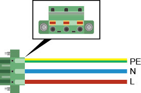

There is a risk of electric shock when handling the Phoenix connector. To avoid electric shock, ensure that wires are connected in the following sequences: red wire (live wire) connects to L; blue wire (neutral wire) connects to N; yellow/green wire (ground cable) connects to PE. In special circumstances, comply with local regulations or customer requirements.
The power cable and Phoenix connector need to be connected onsite. Ensure that there are no exposed metal parts after the power cable is connected to the Phoenix connector.
Specifications
Table 1 lists the specifications of the 3-pin AC power cable.
Minimum Conductor Cross-Sectional Area (for the Power Cable Delivered with the Switch) |
Maximum Conductor Cross-Sectional Area |
|---|---|
0.75 mm2 or 18 AWG NOTE:
The minimum conductor cross-sectional area for the S5720I-28X-PWH-SI-AC series switches is 1.25 mm2 or 16 AWG. |
3 mm2 or 12 AWG |
Connection
One end of the 3-pin AC power cable is used with the Phoenix connector and connected to the AC input port of the S5720I-SI. The other end needs to be made onsite. You can make the power cables according to site requirements and connect the cables to the AC power supply system.