Example for Configuring Agile Distributed SFN Roaming
Configuration Process
You need to configure and maintain WLAN features and functions in different profiles. These WLAN profiles include regulatory domain profile, radio profile, VAP profile, AP system profile, AP wired port profile, WIDS profile, WDS profile, and Mesh profile. When configuring WLAN services, you need to set related parameters in the WLAN profiles and bind the profiles to the AP group or APs. Then the configuration is automatically delivered to and takes effect on the APs. WLAN profiles can reference one another; therefore, you need to know the relationships among the profiles before configuring them. For details about the profile relationships and their basic configuration procedure, see WLAN Service Configuration Procedure.
Networking Requirements
A hospital wants to deploy an agile distributed WLAN to provide WLAN access to doctors and nurses, meeting their basic office requirements. The administrator requires that STA roaming within the coverage area be not perceived by STAs and do not interrupt services.
- AC networking mode: Layer 2 bypass mode
- DHCP deployment mode:
- The AC functions as a DHCP server to assign IP addresses to the central AP and RUs.
- SwitchA functions as a DHCP server to assign IP addresses to STAs.
- Service data forwarding mode: direct forwarding
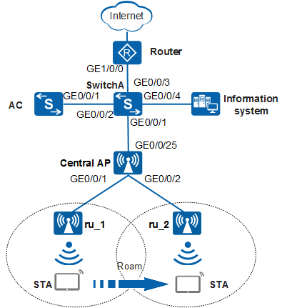
Configuration Roadmap
- Configure the central AP, AC, RUs, and upper-layer devices to communicate at Layer 2.
- Configure DHCP servers to assign IP addresses to the central AP, RUs, and STAs.
- Configure the central AP and RUs to go online.
- Configure WLAN service parameters for STAs to access the WLAN.
- Configure agile distributed SFN roaming.
Item |
Data |
|---|---|
DHCP server |
|
IP address pool for the central AP and RUs |
10.23.100.2-10.23.100.254/24 |
IP address pool for STAs |
10.23.101.3-10.23.101.254/24 |
AC's source interface address |
VLANIF 100: 10.23.100.1/24 |
AP group |
|
Regulatory domain profile |
|
SSID profile |
|
Security profile |
|
VAP Profile |
|
Working channel of RUs |
|
Agile distributed SFN roaming |
Enabled |
Configuration Notes
-
- Agile distributed SFN roaming is supported only by the AD9430DN-12 (including matching RUs) and AD9430DN-24 (including matching RUs). RUs support agile distributed SFN roaming in the following combination modes:
- Between the R230D and R240D (Note: Only the 2.4 GHz radio of the R230D and R240D supports agile distributed SFN roaming, and the 5 GHz radio does not support.)
- Among the R250D, R250D-E, R251D, R251D-E and R450D
For the central AP, after agile distributed SFN roaming is enabled, the total number of agile distributed SFN roaming STAs on a single frequency band (2.4 GHz or 5 GHz) of all RUs does not exceed 128, and that of STAs associated with other VAPs on the same band does not exceed 128.
After agile distributed SFN roaming is enabled, configure all RUs to work on the same channel. When agile distributed SFN roaming is enabled on the 5 GHz frequency band, configure non-radar channels.
RUs involved in roaming must be associated with the same central AP but do not support agile distributed SFN roaming between central APs.
Inter-RU roaming is Layer 2 roaming within a central AP. Agile distributed SFN roaming is not performed on Layer 3.
-
When agile distributed SFN roaming is enabled for both the 2.4 GHz and 5 GHz radios, it is recommended that different SSIDs be used. Otherwise, the radio switchover may occur, affecting user experience.
Agile distributed SFN roaming can be enabled only on one VAP of a radio. If multiple VAPs are configured on a radio, it is recommended that the total VAP rate limit on all VAPs with agile distributed SFN roaming disabled be set to 5 Mbit/s.

If agile distributed SFN roaming is enabled on a VAP of a radio in an AP group, the roaming tracks of all the STAs that are connected to the central AP and associated with the radio may carry the s flag.
Radios enabled with agile distributed SFN roaming do not support channel scanning, channel calibration, or smart roaming.
Agile distributed SFN roaming can be configured based only on AP groups but not based on APs.
RUs involved in agile distributed SFN roaming need to have the following items configured the same:
Procedure
- Set the NAC mode to unified on the AC so that users can connect to the network properly.
<HUAWEI> system-view
[HUAWEI] authentication unified-mode
If the NAC mode is changed from traditional to unified, the unified mode takes effect after you save the configuration and restart the device.
- Configure the network devices.# On SwitchA, add GE0/0/1 to VLAN 100 (management VLAN) and VLAN 101 (service VLAN), set the default VLAN of GE0/0/1 to VLAN 100, add GE0/0/2 to VLAN 100, and add GE0/0/3 and GE0/0/4 to VLAN 101.
<HUAWEI> system-view
[HUAWEI] sysname SwitchA
[SwitchA] vlan batch 100 101
[SwitchA] interface gigabitethernet 0/0/1
[SwitchA-GigabitEthernet0/0/1] port link-type trunk
[SwitchA-GigabitEthernet0/0/1] port trunk pvid vlan 100
[SwitchA-GigabitEthernet0/0/1] port trunk allow-pass vlan 100 101
[SwitchA-GigabitEthernet0/0/1] port-isolate enable
[SwitchA-GigabitEthernet0/0/1] quit
[SwitchA] interface gigabitethernet 0/0/2
[SwitchA-GigabitEthernet0/0/2] port link-type trunk
[SwitchA-GigabitEthernet0/0/2] port trunk allow-pass vlan 100
[SwitchA-GigabitEthernet0/0/2] quit
[SwitchA] interface gigabitethernet 0/0/3
[SwitchA-GigabitEthernet0/0/3] port link-type trunk
[SwitchA-GigabitEthernet0/0/3] port trunk allow-pass vlan 101
[SwitchA-GigabitEthernet0/0/3] quit
[SwitchA] interface gigabitethernet 0/0/4
[SwitchA-GigabitEthernet0/0/4] port link-type trunk
[SwitchA-GigabitEthernet0/0/4] port trunk allow-pass vlan 101
[SwitchA-GigabitEthernet0/0/4] quit
# Configure an IP address for GE1/0/0 on Router.<Huawei> system-view [Huawei] sysname Router [Router] interface gigabitethernet 1/0/0 [Router-GigabitEthernet1/0/0] ip address 10.23.101.2 24 [Router-GigabitEthernet1/0/0] quit
- Configure the AC to communicate with the network devices.# Add GE0/0/1 on the AC to VLAN 100.
[HUAWEI] sysname AC
[AC] vlan batch 100 101
[AC] interface gigabitethernet 0/0/1
[AC-GigabitEthernet0/0/1] port link-type trunk
[AC-GigabitEthernet0/0/1] port trunk allow-pass vlan 100
[AC-GigabitEthernet0/0/1] quit
- Configure DHCP servers to assign IP addresses to the central AP, RUs, and STAs.# On the AC, configure VLANIF 100 to assign IP addresses to the central AP and RUs.
[AC] dhcp enable
[AC] interface vlanif 100
[AC-Vlanif100] ip address 10.23.100.1 24
[AC-Vlanif100] dhcp select interface
[AC-Vlanif100] quit
# On SwitchA, configure VLANIF 101 to assign IP addresses to STAs, and configure a default route with the next hop of the address of Router. Configure the DNS server as required. The common methods are as follows:- In interface address pool scenarios, run the dhcp server dns-list ip-address &<1-8> command in the VLANIF interface view.
- In global address pool scenarios, run the dns-list ip-address &<1-8> command in the IP address pool view.
[SwitchA] dhcp enable
[SwitchA] interface vlanif 101
[SwitchA-Vlanif101] ip address 10.23.101.1 24
[SwitchA-Vlanif101] dhcp select interface
[SwitchA-Vlanif101] dhcp server excluded-ip-address 10.23.101.2
[SwitchA-Vlanif101] quit
[SwitchA] ip route-static 0.0.0.0 0.0.0.0 10.23.101.2
- Configure a central AP and RUs to go online.# Create an AP group to which the APs with the same configuration can be added.
[AC] wlan
[AC-wlan-view] ap-group name ap-group1
[AC-wlan-ap-group-ap-group1] quit
# Create a regulatory domain profile, configure the AC country code in the profile, and apply the profile to the AP group.[AC-wlan-view] regulatory-domain-profile name default [AC-wlan-regulate-domain-default] country-code cn [AC-wlan-regulate-domain-default] quit [AC-wlan-view] ap-group name ap-group1 [AC-wlan-ap-group-ap-group1] regulatory-domain-profile default Warning: Modifying the country code will clear channel, power and antenna gain configurations of the radio and reset the AP. Continue?[Y/N]:y [AC-wlan-ap-group-ap-group1] quit [AC-wlan-view] quit
# Configure the AC's source interface.[AC] capwap source interface vlanif 100
# Import the central AP and RUs offline on the AC and add the central AP and RUs to AP group ap-group1. Assume that the central AP's MAC address is 68a8-2845-62fd, name the central AP central_AP; the RU's MAC addresses are fcb6-9897-c520 and fcb6-9897-ca40, name the RUs ru_1 and ru_2, respectively. The default AP authentication mode is MAC address authentication. If the default settings are retained, you do not need to run the ap auth-mode mac-auth command.
[AC] wlan
[AC-wlan-view] ap auth-mode mac-auth
[AC-wlan-view] ap-id 0 ap-mac 68a8-2845-62fd
[AC-wlan-ap-0] ap-name central_AP
Warning: This operation may cause AP reset. Continue? [Y/N]:y
[AC-wlan-ap-0] ap-group ap-group1
Warning: This operation may cause AP reset. If the country code changes, it will clear channel, power and antenna gain configuration s of the radio, Whether to continue? [Y/N]:y
[AC-wlan-ap-0] quit
[AC-wlan-view] ap-id 1 ap-mac fcb6-9897-c520
[AC-wlan-ap-1] ap-name ru_1
Warning: This operation may cause AP reset. Continue? [Y/N]:y
[AC-wlan-ap-1] ap-group ap-group1
Warning: This operation may cause AP reset. If the country code changes, it will clear channel, power and antenna gain configuration s of the radio, Whether to continue? [Y/N]:y
[AC-wlan-ap-1] quit
[AC-wlan-view] ap-id 2 ap-mac fcb6-9897-ca40
[AC-wlan-ap-2] ap-name ru_2
Warning: This operation may cause AP reset. Continue? [Y/N]:y
[AC-wlan-ap-2] ap-group ap-group1
Warning: This operation may cause AP reset. If the country code changes, it will clear channel, power and antenna gain configuration s of the radio, Whether to continue? [Y/N]:y
[AC-wlan-ap-2] quit
# After the central AP is powered on, run the display ap all command to check the AP state. If the State field is displayed as nor, the RUs go online successfully.
[AC-wlan-view] display ap all Total AP information: nor : normal [3] Extrainfo : Extra information P : insufficient power supply ------------------------------------------------------------------------------------------------------ ID MAC Name Group IP Type State STA Uptime ExtraInfo ------------------------------------------------------------------------------------------------------ 0 68a8-2845-62fd central_AP ap-group1 10.23.100.254 AD9430DN-24 nor 0 2M:25S - 1 fcb6-9897-c520 ru_1 ap-group1 10.23.100.253 R240D nor 0 3M:5S - 2 fcb6-9897-ca40 ru_2 ap-group1 10.23.100.252 R240D nor 0 3M:14S - ------------------------------------------------------------------------------------------------------ Total: 3 - Configure WLAN service parameters.# Create security profile wlan-net and set the security policy in the profile.
In this example, the security policy is set to WPA-WPA2+PSK+AES and password to a1234567. In actual situations, the security policy must be configured according to service requirements.
[AC-wlan-view] security-profile name wlan-net
[AC-wlan-sec-prof-wlan-net] security wpa-wpa2 psk pass-phrase a1234567 aes
[AC-wlan-sec-prof-wlan-net] quit
# Create SSID profile wlan-net and set the SSID name to wlan-net.[AC-wlan-view] ssid-profile name wlan-net [AC-wlan-ssid-prof-wlan-net] ssid wlan-net [AC-wlan-ssid-prof-wlan-net] quit
# Create VAP profile wlan-net, set the data forwarding mode and service VLAN, and apply the security profile and SSID profile to the VAP profile.[AC-wlan-view] vap-profile name wlan-net [AC-wlan-vap-prof-wlan-net] forward-mode direct-forward [AC-wlan-vap-prof-wlan-net] service-vlan vlan-id 101 [AC-wlan-vap-prof-wlan-net] security-profile wlan-net [AC-wlan-vap-prof-wlan-net] ssid-profile wlan-net [AC-wlan-vap-prof-wlan-net] quit
# Bind VAP profile wlan-net to the AP group and apply the profile to radio 0 of the AP.[AC-wlan-view] ap-group name ap-group1 [AC-wlan-ap-group-ap-group1] vap-profile wlan-net wlan 1 radio 0 [AC-wlan-ap-group-ap-group1] quit
- Configure the RU channel and power.
The automatic channel and power calibration function is enabled for radios by default. When this function is enabled, the manual calibration configuration does not take effect. The settings of the RU channel and power in this example are for reference only. You need to configure the RU channel and power based on the actual country code and network planning.
# Disable the automatic channel and power calibration function for radio 0 of RUs, and configure the channel and power for radio 0 of RUs.[AC-wlan-view] ap-id 1 [AC-wlan-ap-1] radio 0 [AC-wlan-radio-1/0] calibrate auto-channel-select disable [AC-wlan-radio-1/0] calibrate auto-txpower-select disable [AC-wlan-radio-1/0] channel 20mhz 6 Warning: This action may cause service interruption. Continue?[Y/N]y [AC-wlan-radio-1/0] eirp 127 [AC-wlan-radio-1/0] quit [AC-wlan-ap-1] quit [AC-wlan-view] ap-id 2 [AC-wlan-ap-2] radio 0 [AC-wlan-radio-2/0] calibrate auto-channel-select disable [AC-wlan-radio-2/0] calibrate auto-txpower-select disable [AC-wlan-radio-2/0] channel 20mhz 6 Warning: This action may cause service interruption. Continue?[Y/N]y [AC-wlan-radio-2/0] eirp 127 [AC-wlan-radio-2/0] quit [AC-wlan-ap-2] quit
- Enable agile distributed SFN roaming.
[AC-wlan-view] vap-profile name wlan-net
[AC-wlan-vap-prof-wlan-net] sfn-roam enable
Warning: This feature requires that radios work on the same channel. Enabling th
is feature will disable the channel calibration, channel scanning, and smart roa
ming functions on the AP and disconnect STAs connected to the VAP. Open, WEP, an
d WAPI encryption modes are not supported. The PSK + WPA2 mode is recommended. A
 radio allows SFN to be enabled only for one VAP. Continue?[Y/N]:y
[AC-wlan-vap-prof-wlan-net] quit
- Configure parameters related to agile distributed SFN roaming.
# Retain the default settings for roaming decision parameters.
# Set radio parameters related to roaming based on the network planning result. The configuration is not mentioned here.
- Verify the configuration.# Run the display vap ssid wlan-net command. If Status in the command output is displayed as ON, the VAPs have been successfully created on the RU radios.
[AC-wlan-view] display vap ssid wlan-net
WID : WLAN ID
--------------------------------------------------------------------------------
AP ID AP name    RfID WID  BSSID          Status  Auth type      STA  SSID
--------------------------------------------------------------------------------
1     ru_1       0    1    68A8-2845-62E0 ON      WPA/WPA2-PSK   0    wlan-net
2     ru_2       0    1    68A8-2845-62E0 ON      WPA/WPA2-PSK   0    wlan-net
--------------------------------------------------------------------------------
Total: 2
# In the coverage area of ru_1, connect a STA to the WLAN with the SSID wlan-net and enter the password a1234567 to associate with the WLAN. Run the display station ssid wlan-net command on the AC. The command output shows that the STA has associated with ru_1.[AC-wlan-view] display station ssid wlan-net Rf/WLAN: Radio ID/WLAN ID Rx/Tx: link receive rate/link transmit rate(Mbps) --------------------------------------------------------------------------------- STA MAC AP ID Ap name Rf/WLAN Band Type Rx/Tx RSSI VLAN IP address --------------------------------------------------------------------------------- e019-1dc7-1e08 1 ru_1 0/1 2.4G 11n 38/64 -68 101 10.23.101.254 --------------------------------------------------------------------------------- Total: 1 2.4G: 1 5G: 0
# When the STA moves from the coverage area of ru_1 to that of ru_2, run the display station ssid wlan-net command on the AC. The command output shows that the STA has associated with ru_2.[AC-wlan-view] display station ssid wlan-net Rf/WLAN: Radio ID/WLAN ID Rx/Tx: link receive rate/link transmit rate(Mbps) ---------------------------------------------------------------------------------------- STA MAC AP ID Ap name Rf/WLAN Band Type Rx/Tx RSSI VLAN IP address ---------------------------------------------------------------------------------------- e019-1dc7-1e08 2 ru_2 0/1 2.4G 11n 38/64 -68 101 10.23.101.254 ---------------------------------------------------------------------------------------- Total: 1 2.4G: 1 5G: 0
# Run the display station roam-track sta-mac e019-1dc7-1e08 command on the AC to check the STA roaming track.[AC-wlan-view] display station roam-track sta-mac e019-1dc7-1e08 Access SSID:wlan-net Rx/Tx:link receive rate/link transmit rate(Mbps) c:PMK Cache Roam r:802.11r Roam s:Same Frequency Network ------------------------------------------------------------------------------ L2/L3 AC IP AP name Radio ID BSSID TIME In/Out RSSI Out Rx/Tx ------------------------------------------------------------------------------ -- 10.23.100.1 ru_1 0 68a8-2845-62e0 2017/10/12 16:52:58 -51/-48 46/13 L2(s) 10.23.100.1 ru_2 1 68a8-2845-62e0 2016/10/12 16:55:45 -58/- -/- ------------------------------------------------------------------------------ Number: 1
Configuration Files
SwitchA configuration file
#
sysname SwitchA
#
vlan batch 100 to 101
#
dhcp enable
#
interface Vlanif101
 ip address 10.23.101.1 255.255.255.0
 dhcp select interface
 dhcp server excluded-ip-address 10.23.101.2
#
interface GigabitEthernet0/0/1
 port link-type trunk
 port trunk pvid vlan 100
 port trunk allow-pass vlan 100 to 101
 port-isolate enable group 1
#
interface GigabitEthernet0/0/2
 port link-type trunk
 port trunk allow-pass vlan 100
#
interface GigabitEthernet0/0/3
 port link-type trunk
 port trunk allow-pass vlan 101
#
interface GigabitEthernet0/0/4
 port link-type trunk
 port trunk allow-pass vlan 101
#
ip route-static 0.0.0.0 0.0.0.0 10.23.101.2
#
return
Router configuration file
#
sysname Router
#
interface GigabitEthernet1/0/0
 ip address 10.23.101.2 255.255.255.0
#
return
AC configuration file
#
sysname AC
#
vlan batch 100 to 101
#
dhcp enable
#
interface Vlanif100
 ip address 10.23.100.1 255.255.255.0
 dhcp select interface
#
interface GigabitEthernet0/0/1
 port link-type trunk
 port trunk allow-pass vlan 100
#
capwap source interface vlanif100
#
wlan
 security-profile name wlan-net
  security wpa-wpa2 psk pass-phrase %^%#m"tz0f>~7.[`^6RWdzwCy16hJj/Mc!,}s`X*B]}A%^%# aes
 ssid-profile name wlan-net
  ssid wlan-net
 vap-profile name wlan-net
  service-vlan vlan-id 101
  sfn-roam enable
  ssid-profile wlan-net
  security-profile wlan-net
 regulatory-domain-profile name default
 ap-group name ap-group1
  radio 0
   vap-profile wlan-net wlan 1
 ap-id 0 type-id 52 ap-mac 68a8-2845-62fd ap-sn 2102350KGF10F8000012
  ap-name central_AP
  ap-group ap-group1
 ap-id 1 type-id 55 ap-mac fcb6-9897-c520 ap-sn 21500826402SF4900166
  ap-name ru_1
  ap-group ap-group1
  radio 0
   channel 20mhz 6
   eirp 127
   calibrate auto-channel-select disable
   calibrate auto-txpower-select disable
 ap-id 2 type-id 55 ap-mac fcb6-9897-ca40 ap-sn 21500826402SF4900207
  ap-name ru_2
  ap-group ap-group1
  radio 0
   channel 20mhz 6
   eirp 127
   calibrate auto-channel-select disable
   calibrate auto-txpower-select disable
#
return