Example for Configuring the Shopping Mall and Supermarket IoT Solution - Hotspot Service and Customer Flow Analysis
Service Requirements
To improve sales and increase profits, a shopping mall wants to promote consumption by pushing customized advertisements to customers.
To meet these requirements, Huawei provides the hotspot service and customer flow analysis solution. This solution provides secure and easy Wi-Fi access for customers and improves user experience. Additionally, the shopping mall can analyze data to find shops that customers are interested in and then push customized advertisements to their mobile phones, promoting consumption.
Networking Requirements
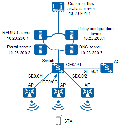
- AC networking mode: Layer 2 in bypass mode
- DHCP deployment mode: Configure an AC as the DHCP server to assign IP addresses to APs and STAs.
- Service data forwarding mode: direct forwarding
Data Planning
Item |
Data |
|---|---|
RADIUS authentication parameters |
Name of the RADIUS authentication scheme: radius_huawei Name of the RADIUS server template: radius_huawei
|
SSL policy |
|
Portal server template |
|
Portal access profile |
|
Authentication profile |
|
Management VLAN |
VLAN 100 |
Service VLAN |
VLAN 101 |
AC's source interface |
VLANIF 100 |
DHCP server |
The AC functions as a DHCP server to assign IP addresses to APs and STAs. |
IP address pool for STAs |
10.23.101.2 to 10.23.101.254/24 |
AP group |
|
Regulatory domain profile |
|
SSID profile |
|
Security profile |
|
VAP profile |
|
Air scan profile |
|
2G radio profile |
|
5G radio profile |
|
Location profile |
|
Host computer |
Customer flow analysis server IP address: 10.23.201.1 Port number: 32180 |
Configuration Roadmap
Configure the AC to communicate with servers.
Configure the AC as a DHCP server to assign IP addresses to APs and STAs.
Configure the APs to go online.
Configure Portal authentication.
Configure WLAN services.
Configure communication parameters between APs and the host computer.
Configure APs' IP addresses on the host computer.
Configuration Notes
- No ACK mechanism is provided for multicast packet transmission on air interfaces. In addition, wireless links are unstable. To ensure stable transmission of multicast packets, they are usually sent at low rates. If a large number of such multicast packets are sent from the network side, the air interfaces may be congested. You are advised to configure multicast packet suppression to reduce impact of a large number of low-rate multicast packets on the wireless network. Exercise caution when configuring the rate limit; otherwise, the multicast services may be affected.
- In direct forwarding mode, you are advised to configure multicast packet suppression on switch interfaces connected to APs.
- In tunnel forwarding mode, you are advised to configure multicast packet suppression in traffic profiles of the AC.
Configure port isolation on the interfaces of the device directly connected to APs. If port isolation is not configured and direct forwarding is used, a large number of unnecessary broadcast packets may be generated in the VLAN, blocking the network and degrading user experience.
In tunnel forwarding mode, the management VLAN and service VLAN cannot be the same. Only packets from the management VLAN are transmitted between the AC and APs. Packets from the service VLAN are not allowed between the AC and APs.
Procedure
- Set the NAC mode to unified on the AC so that users can connect to the network properly.
<HUAWEI> system-view
[HUAWEI] authentication unified-mode

If the NAC mode is changed from traditional to unified, the unified mode takes effect after you save the configuration and restart the device.
- Configure the AC to communicate with servers.
Configure routes based on the actual networking to ensure network interworking between the AC and servers.
- Configure the switch and AC to enable APs to communicate with the AC.
# Configure the access switch. Add GE0/0/1 through GE0/0/4 to VLAN 100 and VLAN 101.
<HUAWEI> system-view
[HUAWEI] sysname Switch
[Switch] vlan batch 100 to 101
[Switch] interface gigabitethernet 0/0/1
[Switch-GigabitEthernet0/0/1] port link-type trunk
[Switch-GigabitEthernet0/0/1] port trunk allow-pass vlan 100 to 101
[Switch-GigabitEthernet0/0/1] quit
[Switch] interface gigabitethernet 0/0/2
[Switch-GigabitEthernet0/0/2] port link-type trunk
[Switch-GigabitEthernet0/0/2] port trunk pvid vlan 100
[Switch-GigabitEthernet0/0/2] port trunk allow-pass vlan 100 to 101
[Switch-GigabitEthernet0/0/2] quit
[Switch] interface gigabitethernet 0/0/3
[Switch-GigabitEthernet0/0/3] port link-type trunk
[Switch-GigabitEthernet0/0/3] port trunk pvid vlan 100
[Switch-GigabitEthernet0/0/3] port trunk allow-pass vlan 100 to 101
[Switch-GigabitEthernet0/0/3] quit
[Switch] interface gigabitethernet 0/0/4
[Switch-GigabitEthernet0/0/4] port link-type trunk
[Switch-GigabitEthernet0/0/4] port trunk pvid vlan 100
[Switch-GigabitEthernet0/0/4] port trunk allow-pass vlan 100 to 101
[Switch-GigabitEthernet0/0/4] quit
# Configure the AC. Add GE0/0/1 to VLAN 100 and VLAN 101.
<HUAWEI> system-view
[HUAWEI] sysname AC
[AC] vlan batch 100 to 101
[AC] interface gigabitethernet 0/0/1
[AC-GigabitEthernet0/0/1] port link-type trunk
[AC-GigabitEthernet0/0/1] port trunk allow-pass vlan 100 to 101
[AC-GigabitEthernet0/0/1] quit
- Configure the AC as a DHCP server to assign IP addresses to APs and STAs.
# Configure the DHCP server based on the address pool of a VLANIF interface.
Configure the DNS server as required. The common methods are as follows:- In interface address pool scenarios, run the dhcp server dns-list ip-address &<1-8> command in the VLANIF interface view.
- In global address pool scenarios, run the dns-list ip-address &<1-8> command in the IP address pool view.
[AC] dhcp enable
[AC] interface vlanif 100
[AC-Vlanif100] ip address 10.23.100.1 24
[AC-Vlanif100] dhcp select interface
[AC-Vlanif100] quit
[AC] interface vlanif 101
[AC-Vlanif101] ip address 10.23.101.1 24
[AC-Vlanif101] dhcp select interface
[AC-Vlanif101] quit
- Configure the APs to go online.# Create an AP group to which APs with the same configuration are to be added.
[AC] wlan
[AC-wlan-view] ap-group name ap-group1
[AC-wlan-ap-group-ap-group1] quit
# Create a regulatory domain profile, configure the country code for the AC in the profile, and bind the profile to the AP group.[AC-wlan-view] regulatory-domain-profile name default [AC-wlan-regulate-domain-default] country-code cn [AC-wlan-regulate-domain-default] quit [AC-wlan-view] ap-group name ap-group1 [AC-wlan-ap-group-ap-group1] regulatory-domain-profile default Warning: Modifying the country code will clear channel, power and antenna gain configurations of the radio and reset the AP. Continue?[Y/N]:y [AC-wlan-ap-group-ap-group1] quit [AC-wlan-view] quit
# Configure the source interface on the AC.[AC] capwap source interface vlanif 100
# Import the AP offline on the AC and add the AP to the AP group ap-group1. Configure an AP name based on the AP's deployment location, so that you can know where the AP is deployed from its name. If the AP with MAC address 60de-4476-e360 is in area 1, name the AP area_1. Add the APs to area_2 and area_3 in the same way. The ap auth-mode command sets the AP authentication mode to MAC address authentication by default. If the default settings are retained, you do not need to run the ap auth-mode mac-auth command.
In this example, the AP4050DN-E is used and has two radios: radio 0 and radio 1.
[AC] wlan
[AC-wlan-view] ap auth-mode mac-auth
[AC-wlan-view] ap-id 0 ap-mac 60de-4476-e360
[AC-wlan-ap-0] ap-name area_1
Warning: This operation may cause AP reset. Continue? [Y/N]:y
[AC-wlan-ap-0] ap-group ap-group1
Warning: This operation may cause AP reset. If the country code changes, it will clear channel, power and antenna gain configuration s of the radio, Whether to continue? [Y/N]:y
[AC-wlan-ap-0] quit
[AC-wlan-view] ap-id 1 ap-mac 60de-4476-e380
[AC-wlan-ap-1] ap-name area_2
Warning: This operation may cause AP reset. Continue? [Y/N]:y
[AC-wlan-ap-1] ap-group ap-group1
Warning: This operation may cause AP reset. If the country code changes, it will clear channel, power and antenna gain configuration s of the radio, Whether to continue? [Y/N]:y
[AC-wlan-ap-1] quit
[AC-wlan-view] ap-id 2 ap-mac 60de-4476-e3a0
[AC-wlan-ap-2] ap-name area_3
Warning: This operation may cause AP reset. Continue? [Y/N]:y
[AC-wlan-ap-2] ap-group ap-group1
Warning: This operation may cause AP reset. If the country code changes, it will clear channel, power and antenna gain configuration s of the radio, Whether to continue? [Y/N]:y
[AC-wlan-ap-2] quit
# After the APs are powered on, run the display ap all command to check the AP states. If the State field displays nor, the APs have gone online.
[AC-wlan-view] display ap all
Total AP information:
nor  : normal          [3]
ExtraInfo : Extra information
P  : insufficient power supply
----------------------------------------------------------------------------------------------
ID   MAC            Name   Group     IP            Type            State STA Uptime ExtraInfo
----------------------------------------------------------------------------------------------
0    60de-4476-e360 area_1 ap-group1 10.23.100.254 AP4050DN-E      nor   0   22S    -
1    60de-4476-e380 area_2 ap-group1 10.23.100.253 AP4050DN-E      nor   0   51S    -
2    60de-4476-e3a0 area_3 ap-group1 10.23.100.252 AP4050DN-E      nor   0   55S    -
----------------------------------------------------------------------------------------------
Total: 3
[AC-wlan-view] quit
- Configure a RADIUS server template, and a RADIUS authentication scheme.
Ensure that the RADIUS server IP address, port number, and shared key are configured correctly and are the same as those on the RADIUS server.
# Configure a RADIUS server template.
[AC] radius-server template radius_huawei
[AC-radius-radius_huawei] radius-server authentication 10.23.200.1 1812
[AC-radius-radius_huawei] radius-server shared-key cipher Huawei@123
[AC-radius-radius_huawei] quit
# Configure a RADIUS authentication scheme.
[AC] aaa
[AC-aaa] authentication-scheme radius_huawei
[AC-aaa-authen-radius_huawei] authentication-mode radius
[AC-aaa-authen-radius_huawei] quit
# Create the authentication domain huawei.com, and bind the AAA authentication scheme radius_huawei and RADIUS server template radius_huawei to the domain.
[AC-aaa] domain huawei.com
[AC-aaa-domain-huawei.com] authentication-scheme radius_huawei
[AC-aaa-domain-huawei.com] radius-server radius_huawei
[AC-aaa-domain-huawei.com] quit
[AC-aaa] quit
# Check whether a user can pass RADIUS authentication. The test user test and password Huawei123 have been configured on the RADIUS server.
[AC] test-aaa test Huawei123 radius-template radius_huawei
Info: Account test succeed.
- Configure Portal authentication.# Enable the Portal interconnection function of the HTTPS protocol.
[AC] portal web-authen-server https ssl-policy https-pol
The SSL policy configuration is not mentioned here. For details, see Web System Login Configuration in the S2720, S5700, and S6700 V200R019C10 Configuration Guide - Basic Configuration.
# Configure the Portal server template abc.[AC] web-auth-server abc [AC-web-auth-server-abc] protocol http password-encrypt uam [AC-web-auth-server-abc] http-method post cmd-key cmd1 [AC-web-auth-server-abc] url https://10.23.200.2:8445/portal [AC-web-auth-server-abc] quit
# Configure the Portal access profile portal1.[AC] portal-access-profile name portal1 [AC-portal-acces-profile-portal1] web-auth-server abc direct [AC-portal-acces-profile-portal1] quit
# Configure the authentication profile p1, bind the Portal access profile portal1 to the authentication profile, specify the domain huawei.com as the forcible authentication domain in the authentication profile, set the user access mode to multi-authen, and set the maximum number of access users to 100.
[AC] authentication-profile name p1
[AC-authen-profile-p1] portal-access-profile portal1
[AC-authen-profile-p1] access-domain huawei.com force
[AC-authen-profile-p1] authentication mode multi-authen max-user 100
[AC-authen-profile-p1] quit
- Configure WLAN services.# Create security profile wlan-net and set the security policy in the profile.
In this example, the security policy is set to WPA-WPA2+PSK+AES and password to a1234567. In actual situations, the security policy must be configured according to service requirements.
[AC-wlan-view] security-profile name wlan-net
[AC-wlan-sec-prof-wlan-net] security wpa-wpa2 psk pass-phrase a1234567 aes
[AC-wlan-sec-prof-wlan-net] quit
# Create SSID profile wlan-net and set the SSID name to wlan-net.[AC-wlan-view] ssid-profile name wlan-net [AC-wlan-ssid-prof-wlan-net] ssid wlan-net [AC-wlan-ssid-prof-wlan-net] quit
# Create VAP profile wlan-vap, configure the data forwarding mode and service VLANs, and apply the security profile, SSID profile, and authentication profile to the VAP profile.[AC-wlan-view] vap-profile name wlan-net [AC-wlan-vap-prof-wlan-net] forward-mode direct-forward [AC-wlan-vap-prof-wlan-net] service-vlan vlan-id 101 [AC-wlan-vap-prof-wlan-net] security-profile wlan-net [AC-wlan-vap-prof-wlan-net] ssid-profile wlan-net [AC-wlan-vap-prof-wlan-net] authentication-profile p1 [AC-wlan-vap-prof-wlan-net] quit
# Bind VAP profile wlan-net to the AP group and apply the profile to radio 0 and radio 1 of the AP.[AC-wlan-view] ap-group name ap-group1 [AC-wlan-ap-group-ap-group1] vap-profile wlan-net wlan 1 radio 0 [AC-wlan-ap-group-ap-group1] vap-profile wlan-net wlan 1 radio 1 [AC-wlan-ap-group-ap-group1] quit
- Configure the air scan function on the AC.# Enter the air scan profile wlan-air-scan and configure an air scan channel set. By default, an air scan channel set contains all channels supported by the corresponding country code of an AP.
[AC-wlan-view] air-scan-profile name wlan-air-scan
[AC-wlan-air-scan-prof-wlan-air-scan] scan-channel-set country-channel
[AC-wlan-air-scan-prof-wlan-air-scan] quit
# Enter the 2G radio profile wlan-radio-2g and bind it to the air scan profile.[AC-wlan-view] radio-2g-profile name wlan-radio-2g [AC-wlan-radio-2g-prof-wlan-radio-2g] air-scan-profile wlan-air-scan [AC-wlan-radio-2g-prof-wlan-radio-2g] quit
# Enter the 5G radio profile wlan-radio-5g and bind it to the air scan profile.[AC-wlan-view] radio-5g-profile name wlan-radio-5g [AC-wlan-radio-5g-prof-wlan-radio-5g] air-scan-profile wlan-air-scan [AC-wlan-radio-5g-prof-wlan-radio-5g] quit
# Enter the AP group ap-group1 and bind it to the radio profiles.[AC-wlan-view] ap-group name ap-group1 [AC-wlan-ap-group-ap-group1] radio-2g-profile wlan-radio-2g radio 0 Warning: This action may cause service interruption. Continue?[Y/N]y [AC-wlan-ap-group-ap-group1] radio-5g-profile wlan-radio-5g radio 1 Warning: This action may cause service interruption. Continue?[Y/N]y [AC-wlan-ap-group-ap-group1] quit
- Configure the Wi-Fi terminal location function.# Create the location profile wlan-location, enable the Wi-Fi terminal location function, and configure the destination IP address and port number for reporting location information.
[AC-wlan-view] location-profile name wlan-location
[AC-wlan-location-prof-wlan-location] private mu-enable
[AC-wlan-location-prof-wlan-location] private server ip-address 10.23.201.1 port 32180 via-ac ac-port 10001
[AC-wlan-location-prof-wlan-location] quit
# Enter the AP group ap-group1 and bind it to the location profile.[AC-wlan-view] ap-group name ap-group1 [AC-wlan-ap-group-ap-group1] location-profile wlan-location radio all Warning: This action may cause service interruption. Continue?[Y/N]y [AC-wlan-ap-group-ap-group1] quit - Add IP addresses of the APs to the host computer and configure the same shared key as that on the APs.
- Verify the configuration.# The WLAN service configuration is automatically delivered to the APs. After completing the configuration, run the display vap ssid wlan-net command. If the Status field displays ON, the VAP has been successfully created on the AP radios.
[AC-wlan-view] display vap ssid wlan-net
WID : WLAN ID
--------------------------------------------------------------------------------
AP ID AP name RfID WID    BSSID          Status  Auth type     STA   SSID
--------------------------------------------------------------------------------
0     area_1  0    1      60DE-4476-E360 ON      WPA/WPA2-PSK  1     wlan-net
0     area_1  1    1      60DE-4476-E370 ON      WPA/WPA2-PSK  0     wlan-net
1     area_2  0    1      60DE-4476-E380 ON      WPA/WPA2-PSK  1     wlan-net
1     area_2  1    1      60DE-4476-E390 ON      WPA/WPA2-PSK  0     wlan-net
2     area_3  0    1      60DE-4476-E3a0 ON      WPA/WPA2-PSK  1     wlan-net
2     area_3  1    1      60DE-4476-E3b0 ON      WPA/WPA2-PSK  0     wlan-net
------------------------------------------------------------------------------------
Total: 6
# View the location profile configuration.[AC-wlan-view] display location-profile name wlan-location -------------------------------------------------------------------------------- ... private mu : enable private server : 10.23.201.1 private server domain : - private server port : 32180 private via-AC : enable private via-AC port : 10001 private report-frequency(ms) : 20000 private report-protocol : udp private mu protocol-version : v3 --------------------------------------------------------------------------------
# STAs can discover the wireless network with SSID wlan-net and associate with it after successful Portal authentication.
Configuration Files
Access switch configuration file
#
sysname Switch
#
vlan batch 100 to 101
#
interface GigabitEthernet0/0/1
 port link-type trunk
 port trunk allow-pass vlan 100 to 101
#
interface GigabitEthernet0/0/2
 port link-type trunk
 port trunk pvid vlan 100
 port trunk allow-pass vlan 100 to 101
#
interface GigabitEthernet0/0/3
 port link-type trunk
 port trunk pvid vlan 100
 port trunk allow-pass vlan 100 to 101
#
interface GigabitEthernet0/0/4
 port link-type trunk
 port trunk pvid vlan 100
 port trunk allow-pass vlan 100 to 101
#
return
AC configuration file
#
 sysname AC
#
vlan batch 100 to 101
#
authentication-profile name p1
 portal-access-profile portal1
 authentication mode multi-authen max-user 100
 access-domain huawei.com force
#
dhcp enable
#
radius-server template radius_huawei
 radius-server shared-key cipher %^%#Y+{_U['QgLX705'xUi3H-cXD0\iPHM~}c<8*IHl.%^%#
 radius-server authentication 10.23.200.1 1812 weight 80
#
web-auth-server abc
 port 50100
 url https://10.23.200.2:8445/portal
 protocol http password-encrypt uam
 http-method post cmd-key cmd1
#
portal-access-profile name portal1
 web-auth-server abc direct
#
aaa
 authentication-scheme radius_huawei
  authentication-mode radius
 domain huawei.com
  authentication-scheme radius_huawei
  radius-server radius_huawei
#
interface Vlanif100
 ip address 10.23.100.1 255.255.255.0
 dhcp select interface
#
interface Vlanif101
 ip address 10.23.101.1 255.255.255.0
 dhcp select interface
#
interface GigabitEthernet0/0/1
 port link-type trunk
 port trunk allow-pass vlan 100 to 101
#
portal web-authen-server https ssl-policy https-pol
#
capwap source interface vlanif100
#
wlan
 security-profile name wlan-net
  security wpa-wpa2 psk pass-phrase %^%#*T~tI'mg@M*b6+.;NNq)`i[97LZlK~X_nSVeOEBO%^%# aes
 ssid-profile name wlan-net
  ssid wlan-net
 vap-profile name wlan-net
  service-vlan vlan-id 101
  ssid-profile wlan-net
  security-profile wlan-net
  authentication-profile p1
 location-profile name wlan-location
  private mu-enable
  private server ip-address 10.23.201.1 port 32180 via-ac ac-port 10001
 regulatory-domain-profile name default
 air-scan-profile name wlan-air-scan
 radio-2g-profile name wlan-radio-2g
  air-scan-profile wlan-air-scan
 radio-5g-profile name wlan-radio-5g
  air-scan-profile wlan-air-scan
 ap-group name ap-group1
  location-profile wlan-location radio all
  radio 0
   radio-2g-profile wlan-radio-2g
   vap-profile wlan-net wlan 1
  radio 1
   radio-5g-profile wlan-radio-5g
   vap-profile wlan-net wlan 1
 ap-id 0 ap-mac 60de-4476-e360 ap-sn 210235419610D2000066
  ap-name area_1
  ap-group ap-group1
 ap-id 1 ap-mac 60de-4476-e380 ap-sn 210235419610D2000067
  ap-name area_2
  ap-group ap-group1
 ap-id 2 ap-mac 60de-4476-e3a0 ap-sn 210235419610D2000068
  ap-name area_3
  ap-group ap-group1
#
return