Example for Configuring the Education IoT Solution - Student Health and Safety
Service Requirements
A school pays much attention to health and safety of its students, and desires to use technical methods to monitor and query students' health and safety information.
To meet these requirements, Huawei provides the Student Health and Safety IoT Solution that reuses the existing WLAN.
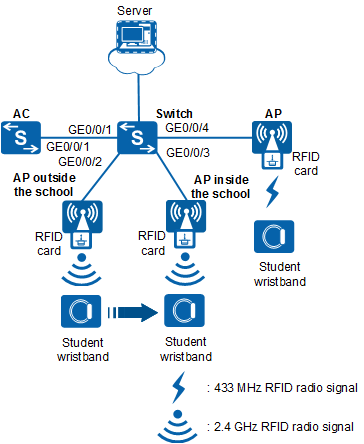
Networking Requirements
- AC networking mode: Layer 2 in bypass mode
- DHCP deployment mode: Configure an AC as the DHCP server to assign IP addresses to APs and STAs.
- Service data forwarding mode: direct forwarding
Data Planning
Item |
Data |
|---|---|
Management VLAN |
VLAN 100 |
Service VLAN |
VLAN 101 |
AC's source interface |
VLANIF 100 |
DHCP server |
The AC functions as a DHCP server to assign IP addresses to APs and STAs. |
IP address pool for STAs |
10.23.101.2 to 10.23.101.254/24 |
AP group |
|
Regulatory domain profile |
|
SSID profile |
|
Security profile |
|
VAP profile |
|
IoT profile |
|
Configuration Roadmap
Configure network interworking of the APs, switch, AC, and host computer.
Configure the AC as a DHCP server to assign IP addresses to APs and STAs.
Configure the APs to go online.
Configure WLAN services.
Configure communication parameters between the APs and host computer.
Add IP addresses of the APs to the host computer and configure the same shared key as that on the APs.
Configuration Notes
- No ACK mechanism is provided for multicast packet transmission on air interfaces. In addition, wireless links are unstable. To ensure stable transmission of multicast packets, they are usually sent at low rates. If a large number of such multicast packets are sent from the network side, the air interfaces may be congested. You are advised to configure multicast packet suppression to reduce impact of a large number of low-rate multicast packets on the wireless network. Exercise caution when configuring the rate limit; otherwise, the multicast services may be affected.
- In direct forwarding mode, you are advised to configure multicast packet suppression on switch interfaces connected to APs.
- In tunnel forwarding mode, you are advised to configure multicast packet suppression in traffic profiles of the AC.
Configure port isolation on the interfaces of the device directly connected to APs. If port isolation is not configured and direct forwarding is used, a large number of unnecessary broadcast packets may be generated in the VLAN, blocking the network and degrading user experience.
In tunnel forwarding mode, the management VLAN and service VLAN cannot be the same. Only packets from the management VLAN are transmitted between the AC and APs. Packets from the service VLAN are not allowed between the AC and APs.
Procedure
- Set the NAC mode to unified on the AC so that users can connect to the network properly.
<HUAWEI> system-view
[HUAWEI] authentication unified-mode

If the NAC mode is changed from traditional to unified, the unified mode takes effect after you save the configuration and restart the device.
- Configure the switch and AC to enable APs to communicate with the AC.
# Configure the access switch. Add GE0/0/1 through GE0/0/4 to VLAN 100 (management VLAN) and VLAN 101 (service VLANs).
<HUAWEI> system-view
[HUAWEI] sysname Switch
[Switch] vlan batch 100 to 101
[Switch] interface gigabitethernet 0/0/1
[Switch-GigabitEthernet0/0/1] port link-type trunk
[Switch-GigabitEthernet0/0/1] port trunk allow-pass vlan 100 to 101
[Switch-GigabitEthernet0/0/1] quit
[Switch] interface gigabitethernet 0/0/2
[Switch-GigabitEthernet0/0/2] port link-type trunk
[Switch-GigabitEthernet0/0/2] port trunk pvid vlan 100
[Switch-GigabitEthernet0/0/2] port trunk allow-pass vlan 100 to 101
[Switch-GigabitEthernet0/0/2] quit
[Switch] interface gigabitethernet 0/0/3
[Switch-GigabitEthernet0/0/3] port link-type trunk
[Switch-GigabitEthernet0/0/3] port trunk pvid vlan 100
[Switch-GigabitEthernet0/0/3] port trunk allow-pass vlan 100 to 101
[Switch-GigabitEthernet0/0/3] quit
[Switch] interface gigabitethernet 0/0/4
[Switch-GigabitEthernet0/0/4] port link-type trunk
[Switch-GigabitEthernet0/0/4] port trunk pvid vlan 100
[Switch-GigabitEthernet0/0/4] port trunk allow-pass vlan 100 to 101
[Switch-GigabitEthernet0/0/4] quit
# Configure the AC. Add GE0/0/1 to VLAN 100 and VLAN 101.
<HUAWEI> system-view
[HUAWEI] sysname AC
[AC] vlan batch 100 to 101
[AC] interface gigabitethernet 0/0/1
[AC-GigabitEthernet0/0/1] port link-type trunk
[AC-GigabitEthernet0/0/1] port trunk allow-pass vlan 100 to 101
[AC-GigabitEthernet0/0/1] quit
- Configure network interworking between the APs and server.
Configure routes based on the actual networking situation to ensure network interworking between the APs and host computer.
- Configure the AC as a DHCP server to assign IP addresses to APs and STAs.
# Configure the DHCP server based on the address pool of a VLANIF interface.
Configure the DNS server as required. The common methods are as follows:- In interface address pool scenarios, run the dhcp server dns-list ip-address &<1-8> command in the VLANIF interface view.
- In global address pool scenarios, run the dns-list ip-address &<1-8> command in the IP address pool view.
[AC] dhcp enable
[AC] interface vlanif 100
[AC-Vlanif100] ip address 10.23.100.1 24
[AC-Vlanif100] dhcp select interface
[AC-Vlanif100] quit
[AC] interface vlanif 101
[AC-Vlanif101] ip address 10.23.101.1 24
[AC-Vlanif101] dhcp select interface
[AC-Vlanif101] quit
- Configure the APs to go online.# Create an AP group to which APs with the same configuration are to be added.
[AC] wlan
[AC-wlan-view] ap-group name ap-group1
[AC-wlan-ap-group-ap-group1] quit
# Create a regulatory domain profile, configure the country code for the AC in the profile, and bind the profile to the AP group.[AC-wlan-view] regulatory-domain-profile name default [AC-wlan-regulate-domain-default] country-code cn [AC-wlan-regulate-domain-default] quit [AC-wlan-view] ap-group name ap-group1 [AC-wlan-ap-group-ap-group1] regulatory-domain-profile default Warning: Modifying the country code will clear channel, power and antenna gain configurations of the radio and reset the AP. Continue?[Y/N]:y [AC-wlan-ap-group-ap-group1] quit [AC-wlan-view] quit
# Configure the source interface on the AC.[AC] capwap source interface vlanif 100
# Import APs offline on the AC and add the APs to the AP group ap-group1. Configure an AP name based on the AP's deployment location, so that you can know where the AP is deployed from its name. For example, if an AP with MAC address 60de-4476-e360 is deployed in a classroom, name the AP room_1. If the APs with MAC addresses 60de-4476-e460 and 60de-4476-e560 are deployed inside and outside the school door, name the APs door_1 and door_2. The ap auth-mode command sets the AP authentication mode to MAC address authentication by default. If the default settings are retained, you do not need to run the ap auth-mode mac-auth command.
In this example, the AP4050DN-E is used and has two radios: radio 0 and radio 1.
[AC] wlan
[AC-wlan-view] ap auth-mode mac-auth
[AC-wlan-view] ap-id 0 ap-mac 60de-4476-e360
[AC-wlan-ap-0] ap-name room_1
Warning: This operation may cause AP reset. Continue? [Y/N]:y
[AC-wlan-ap-0] ap-group ap-group1
Warning: This operation may cause AP reset. If the country code changes, it will clear channel, power and antenna gain configuration s of the radio, Whether to continue? [Y/N]:y
[AC-wlan-ap-0] quit
[AC-wlan-view] ap-id 1 ap-mac 60de-4476-e460
[AC-wlan-ap-1] ap-name door_1
Warning: This operation may cause AP reset. Continue? [Y/N]:y
[AC-wlan-ap-1] ap-group ap-group1
Warning: This operation may cause AP reset. If the country code changes, it will clear channel, power and antenna gain configuration s of the radio, Whether to continue? [Y/N]:y
[AC-wlan-ap-1] quit
[AC-wlan-view] ap-id 2 ap-mac 60de-4476-e560
[AC-wlan-ap-2] ap-name door_2
Warning: This operation may cause AP reset. Continue? [Y/N]:y
[AC-wlan-ap-2] ap-group ap-group1
Warning: This operation may cause AP reset. If the country code changes, it will clear channel, power and antenna gain configuration s of the radio, Whether to continue? [Y/N]:y
[AC-wlan-ap-2] quit
# After the APs are powered on, run the display ap all command to check the AP states. If the State field displays nor, the APs have gone online.
[AC-wlan-view] display ap all
Total AP information:
nor  : normal          [3]
ExtraInfo : Extra information
P  : insufficient power supply
----------------------------------------------------------------------------------------------
ID   MAC            Name   Group     IP            Type            State STA Uptime ExtraInfo
----------------------------------------------------------------------------------------------
0    60de-4476-e360 room_1 ap-group1 10.23.100.254 AP4050DN-E      nor   0   51S    -
1    60de-4476-e460 door_1 ap-group1 10.23.100.253 AP4050DN-E      nor   0   45S    -
2    60de-4476-e560 door_2 ap-group1 10.23.100.252 AP4050DN-E      nor   0   25S    -
----------------------------------------------------------------------------------------------
Total: 3
- Configure WLAN services.# Create security profile wlan-net and set the security policy in the profile.
In this example, the security policy is set to WPA-WPA2+PSK+AES and password to a1234567. In actual situations, the security policy must be configured according to service requirements.
[AC-wlan-view] security-profile name wlan-net
[AC-wlan-sec-prof-wlan-net] security wpa-wpa2 psk pass-phrase a1234567 aes
[AC-wlan-sec-prof-wlan-net] quit
# Create SSID profile wlan-net and set the SSID name to wlan-net.[AC-wlan-view] ssid-profile name wlan-net [AC-wlan-ssid-prof-wlan-net] ssid wlan-net [AC-wlan-ssid-prof-wlan-net] quit
# Create VAP profile wlan-net, set the data forwarding mode and service VLAN, and apply the security profile and SSID profile to the VAP profile.[AC-wlan-view] vap-profile name wlan-net [AC-wlan-vap-prof-wlan-net] forward-mode direct-forward [AC-wlan-vap-prof-wlan-net] service-vlan vlan-id 101 [AC-wlan-vap-prof-wlan-net] security-profile wlan-net [AC-wlan-vap-prof-wlan-net] ssid-profile wlan-net [AC-wlan-vap-prof-wlan-net] quit
# Bind VAP profile wlan-net to the AP group and apply the profile to radio 0 and radio 1 of the AP.[AC-wlan-view] ap-group name ap-group1 [AC-wlan-ap-group-ap-group1] vap-profile wlan-net wlan 1 radio 0 [AC-wlan-ap-group-ap-group1] vap-profile wlan-net wlan 1 radio 1 [AC-wlan-ap-group-ap-group1] quit
- Configure communication parameters between the APs and host computer.
[AC-wlan-view] iot-profile name wlan-iot
[AC-wlan-iot-prof-wlan-iot] management-server server-ip 10.23.200.1 server-port 3000
[AC-wlan-iot-prof-wlan-iot] config-agent permit ip-address 10.23.102.253 255.255.255.0
[AC-wlan-iot-prof-wlan-iot] share-key aabb0011@11
[AC-wlan-iot-prof-wlan-iot] quit
[AC-wlan-view] ap-group name ap-group1
[AC-wlan-ap-group-ap-group1] card 1
[AC-wlan-group-card-ap-group1/1] iot-profile wlan-iot config-agent tcp port 50200
[AC-wlan-group-card-ap-group1/1] quit
[AC-wlan-ap-group-ap-group1] quit
- Add IP addresses of the APs to the host computer and configure the same shared key as that on the APs.
- Verify the configuration.# The WLAN service configuration is automatically delivered to the APs. After completing the configuration, run the display vap ssid wlan-net command. If the Status field displays ON, the VAP has been successfully created on the AP radios.
[AC-wlan-view] display vap ssid wlan-net
WID : WLAN ID
--------------------------------------------------------------------------------
AP ID AP name RfID WID    BSSID          Status  Auth type     STA   SSID
--------------------------------------------------------------------------------
0     room_1  0    1      60DE-4476-E360 ON      WPA/WPA2-PSK  1     wlan-net
0     room_1  1    1      60DE-4476-E370 ON      WPA/WPA2-PSK  0     wlan-net
0     door_1  0    1      60DE-4476-E460 ON      WPA/WPA2-PSK  1     wlan-net
0     door_1  1    1      60DE-4476-E470 ON      WPA/WPA2-PSK  0     wlan-net
0     door_2  0    1      60DE-4476-E560 ON      WPA/WPA2-PSK  1     wlan-net
0     door_2  1    1      60DE-4476-E570 ON      WPA/WPA2-PSK  0     wlan-net
------------------------------------------------------------------------------------
Total: 6
# Check the IoT profile configuration.[AC-wlan-view] display iot-profile name wlan-iot -------------------------------------------------------------------------------- Type : common Agent permit IP address : 10.23.102.253 Agent permit net-mask : 255.255.255.0 Management server IP address : 10.23.200.1 Management server port : 3000 ExtManagement server IP address : - ExtManagement server port : - Share key : ****** --------------------------------------------------------------------------------
Configuration Files
Access switch configuration file
#
sysname Switch
#
vlan batch 100 to 101
#
interface GigabitEthernet0/0/1
 port link-type trunk
 port trunk allow-pass vlan 100 to 101
#
interface GigabitEthernet0/0/2
 port link-type trunk
 port trunk pvid vlan 100
 port trunk allow-pass vlan 100 to 101
#
interface GigabitEthernet0/0/3
 port link-type trunk
 port trunk pvid vlan 100
 port trunk allow-pass vlan 100 to 101
#
interface GigabitEthernet0/0/4
 port link-type trunk
 port trunk pvid vlan 100
 port trunk allow-pass vlan 100 to 101
#
return
AC configuration file
#
 sysname AC
#
vlan batch 100 to 101
#
dhcp enable
#
interface Vlanif100
 ip address 10.23.100.1 255.255.255.0
 dhcp select interface
#
interface Vlanif101
 ip address 10.23.101.1 255.255.255.0
 dhcp select interface
#
interface GigabitEthernet0/0/1
 port link-type trunk
 port trunk allow-pass vlan 100 to 101
#
capwap source interface vlanif100
#
wlan
 security-profile name wlan-net
  security wpa-wpa2 psk pass-phrase %^%#CU9SYQg[.Vxx;xH%>nwFA.WJ6i/Fm~me>&W%`b/-%^%# aes
 ssid-profile name wlan-net
  ssid wlan-net
 vap-profile name wlan-net
  service-vlan vlan-id 101
  ssid-profile wlan-net
  security-profile wlan-net
 regulatory-domain-profile name default
 iot-profile name wlan-iot
  config-agent permit ip-address 10.23.102.253 255.255.255.0
  management-server server-ip 10.23.200.1 server-port 3000
  share-key %^%#vj*JIT.]q%6Q6[VqoHMJHs(5Oss3g3*%@r9Vy%aW%^%#
 ap-group name ap-group1
  radio 0
   vap-profile wlan-net wlan 1
  radio 1
   vap-profile wlan-net wlan 1
  card 1
   iot-profile wlan-iot config-agent tcp port 50200
 ap-id 0 ap-mac 60de-4476-e360 ap-sn 210235419610D2000066
  ap-name room_1
  ap-group ap-group1
 ap-id 1 ap-mac 60de-4476-e460 ap-sn 210235419610D2000067
  ap-name door_1
  ap-group ap-group1
 ap-id 2 ap-mac 60de-4476-e560 ap-sn 210235419610D2000068
  ap-name door_2
  ap-group ap-group1
#
return