lldp tlv-enable legacy-tlv pnp startup-vlan
Function
The lldp tlv-enable legacy-tlv pnp startup-vlan command enables a switch to send LLDP packets containing PnP VLAN information to downstream devices.
The undo lldp tlv-enable legacy-tlv pnp startup-vlan command disables a switch from sending LLDP packets containing PnP VLAN information to downstream devices.
By default, the switch is configured to send LLDP packets containing PnP VLAN information to downstream devices.
Views
Ethernet interface view, GE interface view, XGE interface view, MultiGE interface view, 40GE interface view, 100GE interface view, 25GE interface view
Usage Guidelines
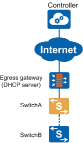
Scenario 1: All switches on a CloudCampus network can be managed by iMaster NCE-Campus.
On the CloudCampus network shown in Figure 1, SwitchA and SwitchB are both switches. the VLAN for the IP address pool of the DHCP server is not VLAN 1, and SwitchB is newly connected to the network. After SwitchB is connected to the network, it uses the management VLAN 1 to send a request packet to the DHCP server to obtain the NETCONF enabling configuration, IP address, and information of iMaster NCE-Campus. The VLAN for the IP address pool of the DHCP server is not VLAN 1. As a result, SwitchB cannot obtain the related information.To address the problem, configure PnP VLAN auto-negotiation on SwitchA. After SwitchB starts, SwitchA transmits the PnP VLAN ID to SwitchB through PnP VLAN auto-negotiation, so that SwitchB can use the PnP VLAN to obtain the related information from the DHCP server.
SwitchA can transmit the PnP VLAN ID to SwitchB only when SwitchA meets the following conditions:- SwitchA has registered with iMaster NCE-Campus successfully.
- iMaster NCE-Campus has delivered a PnP VLAN ID to SwitchA, and the configuration file contains the pnp startup-vlan vlan-id command or SwitchA has negotiated a PnP VLAN ID with its upstream device.
- iMaster NCE-Campus has delivered to SwitchA the function of transmitting the PnP VLAN ID to its downstream device, and the configuration file contains the pnp startup-vlan send enable command.
- SwitchA is enabled to send LLDP packets containing PnP VLAN information to its downstream device. This function is enabled by default. If the configuration file contains the undo lldp tlv-enable legacy-tlv pnp startup-vlan command, the function of sending LLDP packets containing the PnP VLAN ID to the downstream device is disabled. You can enable the function on iMaster NCE-Campus.
SwitchB can obtain the PnP VLAN ID transmitted by SwitchA only after SwitchB is enabled to receive the PnP VLAN negotiation packets sent by its upstream device. This function is enabled by default. If the configuration file contains the undo pnp startup-vlan receive enable command, the function of receiving the PnP VLAN negotiation packets sent by the upstream device is disabled. You can enable the function on iMaster NCE-Campus.
The function of transmitting the PnP VLAN ID to the downstream device and the PnP VLAN ID can be preconfigured on and delivered to a switch after the switch has registered with iMaster NCE-Campus.
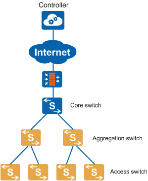
Scenario 2: On a CloudCampus network, some switches cannot be managed by iMaster NCE-Campus.
On the CloudCampus network shown in Figure 2, the access and aggregation switches can be managed by iMaster NCE-Campus. The core switch is not managed by iMaster NCE-Campus. When the management VLAN is changed on iMaster NCE-Campus from VLAN 1 (default) to VLAN 2, the core switch needs to notify its downstream switches of the new management VLAN ID.Configure PnP VLAN auto-negotiation on the core switch so that the core switch can notify its downstream switches of the new management VLAN ID. This process consists of the following operations:- Run the pnp startup-vlan command to configure a PnP VLAN ID.
- Run the pnp startup-vlan send enable command to enable the switch to transmit the PnP VLAN ID to its downstream devices.
- Run the lldp tlv-enable legacy-tlv pnp startup-vlan command to enable the switch to send LLDP packets containing PnP VLAN information to its downstream devices. This function is enabled by default. After this function is enabled, LLDP protocol packets contain PnP VLAN information, including the PnP VLAN ID, the flag indicating whether to establish an Eth-Trunk, and the flag indicating whether an Eth-Trunk works in LACP mode.
- If the core switch and the aggregation switches are connected through Eth-Trunks, you also need to run the pnp startup-link-aggregation enable command to enable the function of notifying downstream devices of the need to establish an Eth-Trunk. After the command is run, the downstream devices will automatically add interfaces to Eth-Trunks based on the negotiation.
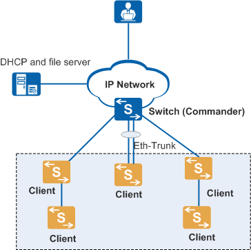
Scenario 3: Zero-touch deployment using EasyDeploy
In Figure 3, when EasyDeploy is used for zero touch deployment, the Commander needs to notify a client of the new VLAN ID if the Commander does not use VLAN 1 to communicate with the client.Configure PnP VLAN auto-negotiation on the Commander to enable the Commander to notify clients of the new VLAN ID. This process consists of the following operations:- Run the pnp startup-vlan command to configure a PnP VLAN ID.
- Run the pnp startup-vlan send enable command to enable the switch to transmit the PnP VLAN ID to its downstream devices.
- Run the lldp tlv-enable legacy-tlv pnp startup-vlan command to enable the switch to send LLDP packets containing PnP VLAN information to its downstream devices. This function is enabled by default. After this function is enabled, LLDP protocol packets contain PnP VLAN information, including the PnP VLAN ID, the flag indicating whether to establish an Eth-Trunk, and the flag indicating whether an Eth-Trunk works in LACP mode.
- If the core switch and the aggregation switches are connected through Eth-Trunks, you also need to run the pnp startup-link-aggregation enable command to enable the function of notifying downstream devices of the need to establish an Eth-Trunk. After the command is run, the downstream devices will automatically add interfaces to Eth-Trunks based on the negotiation.