Example for Configuring the Access Layer for a Wired Campus Network Using eSight (eSight V300R005C00 and Earlier Versions)
Prerequisites
- SNMP read and write communities have been configured for devices. In addition, the devices have been added to eSight, and can successfully communicate with eSight.
- Telnet parameters have been configured on eSight.
- The LLDP protocol has been enabled on SVF-capable devices.
Networking Requirements
Company M has constructed a wired campus network on which many access devices are deployed sparsely. It is difficult to manage and configure these access devices. The network administrator Jack requires that he can uniformly manage and configure the access devices to reduce management costs.
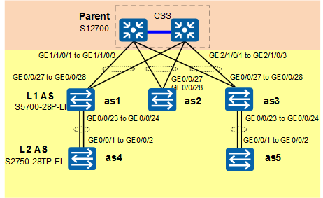
As shown in Figure 1, two switches at the aggregation layer form a cluster and function as the parents to connect to multiple access switches (ASs).
In this example, the S12708, S5700-28P-LI, and S2750-28TP-EI are used as the parent, level-1 AS, and level-2 AS, respectively. The eSight software version is V300R005C00.
Configuration Roadmap
- Configure CSS/iStack on the parents to ensure high reliability of the super virtual fabric (SVF) system.
Configure SVF system capabilities.
- Create an SVF enabling template to enable SVF on the parent and configure the SVF client management IP address pool, file server, and forwarding mode.
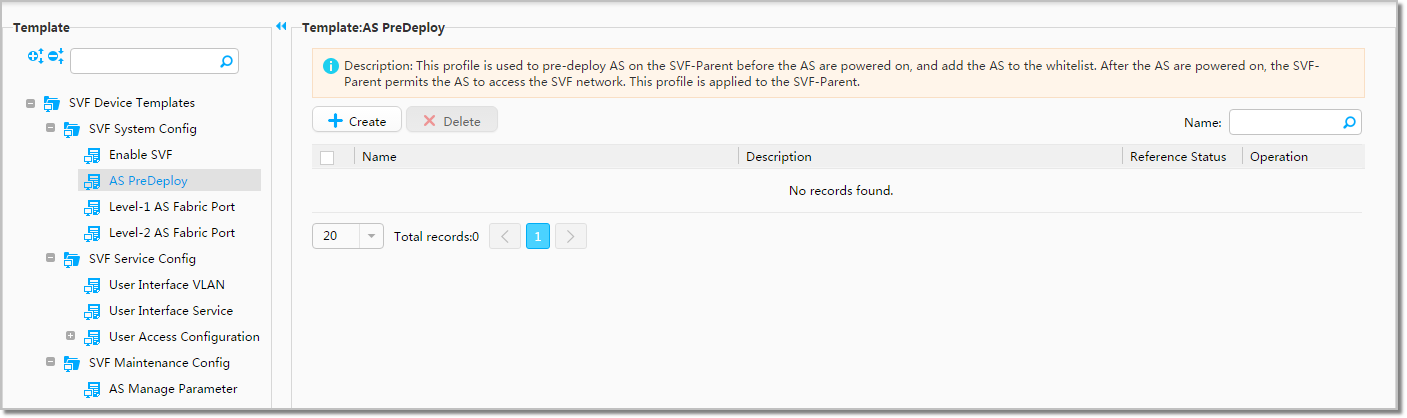
- Create an AS predeployment template to predeploy ASs on the SVF parent before powering on them and add the ASs to a whitelist. After the ASs are powered on, the SVF parent permits the ASs to access the SVF network.
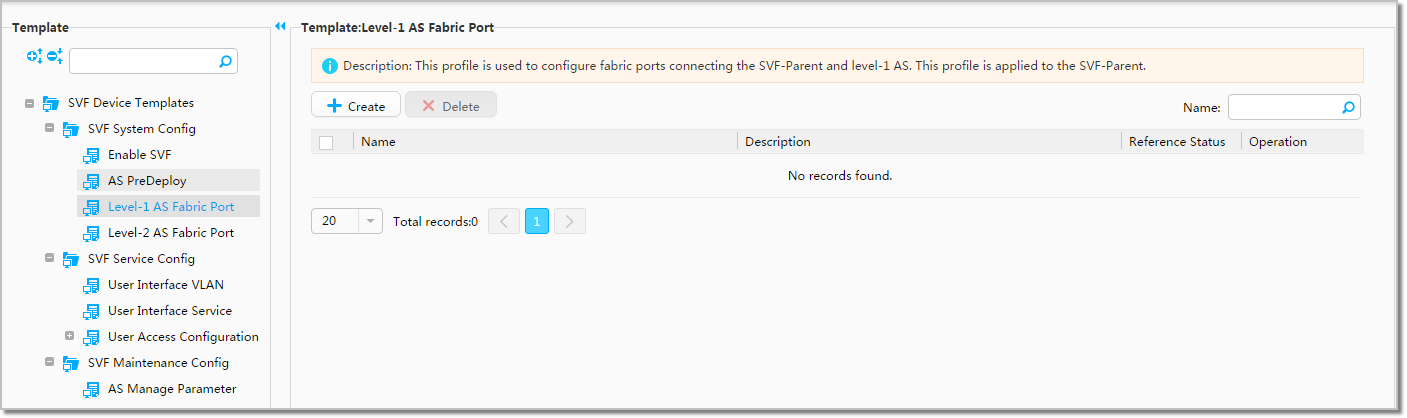
- Create a level-1 AS fabric port template to set parameters for the fabric ports that connect the SVF parent to level-1 ASs.
- Create a level-2 AS fabric port template to set parameters for the fabric ports that connect level-1 ASs to level-2 ASs.
- Create a system configuration matrix to deploy the template instances to the SVF parent.
- Clear the configurations of ASs, restart the ASs, and then connect the parent to level-1 ASs and level-1 ASs to level-2 ASs using cables.
Configure SVF service capabilities.
- Create port groups.
- Create user interface VLAN templates to set pass VLANs for user-side ports.
- Create a user interface service template to set network security parameters for user-side ports.
- Create a service configuration matrix to deploy the template instances to the port groups.
Data Plan
Group Name |
Device Name |
Device IP |
|---|---|---|
SVF Parent |
SVF-S12708 |
10.137.240.114 |
Group Name |
Device |
Port |
|---|---|---|
PortGroup1 |
as1 |
ALL |
PortGroup1 |
as2 |
ALL |
PortGroup1 |
as4 |
ALL |
PortGroup2 |
as3 |
ALL |
PortGroup2 |
as5 |
ALL |
Instance Name |
VLAN ID |
IP Address |
Mask |
|---|---|---|---|
Temp1 |
11 |
192.168.11.1 |
24 |
Instance Name |
AS Name |
AS Type |
MAC Address |
Whether the AS Is Added to Whitelist |
|---|---|---|---|---|
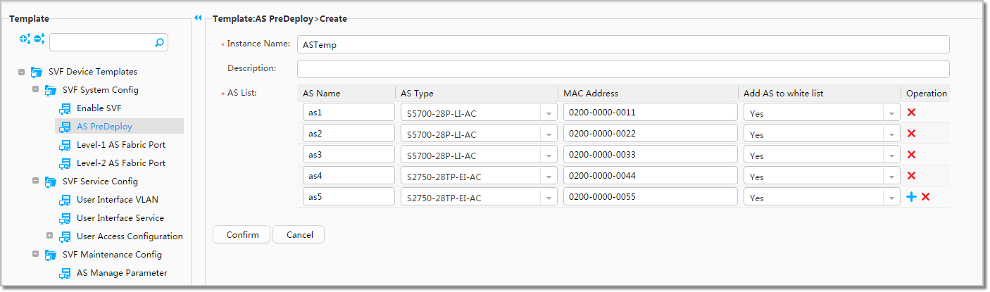
ASTemp |
as1 |
S5700-28P-LI-AC |
0200-0000-0011 |
Yes |
as2 |
S5700-28P-LI-AC |
0200-0000-0022 |
Yes |
|
as3 |
S5700-28P-LI-AC |
0200-0000-0033 |
Yes |
|
as4 |
S2750-28TP-EI-AC |
0200-0000-0044 |
Yes |
|
as5 |
S2750-28TP-EI-AC |
0200-0000-0055 |
Yes |
Instance Name |
Fabric Port ID |
Eth-Trunk ID |
GE Interface Number |
|---|---|---|---|
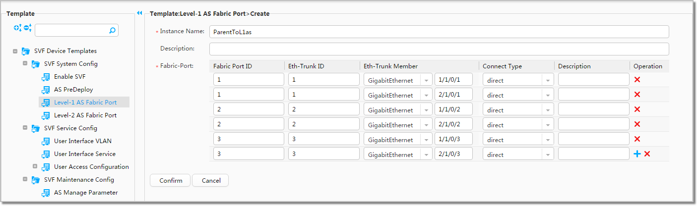
ParentToL1as |
1 |
1 |
1/1/0/1 |
1 |
1 |
2/1/0/1 |
|
2 |
2 |
1/1/0/2 |
|
2 |
2 |
2/1/0/2 |
|
3 |
3 |
1/1/0/3 |
|
3 |
3 |
2/1/0/3 |
Instance Name |
AS Name |
Fabric Port ID |
Eth-Trunk ID |
GE Interface Number |
|---|---|---|---|---|
L2AS |
1 |
4 |
4 |
0/0/23 |
1 |
4 |
4 |
0/0/24 |
|
3 |
5 |
5 |
0/0/23 |
|
3 |
5 |
5 |
0/0/24 |
Instance Name |
Default VLAN |
|---|---|
VLAN10 |
10 |
VLAN20 |
20 |
Instance Name |
User Access Port |
|---|---|
AccessTemp |
ON |
Procedure
- Configure CSS/iStack on the parents to ensure high reliability of the super virtual fabric (SVF) system. For details, see "CSS Configuration" or "Stack Configuration".
- Create a template instance and enable SVF on the parent.
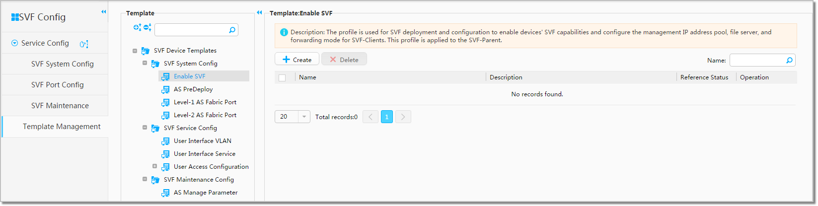
- Choose from the navigation tree, choose in Template, and click Create.
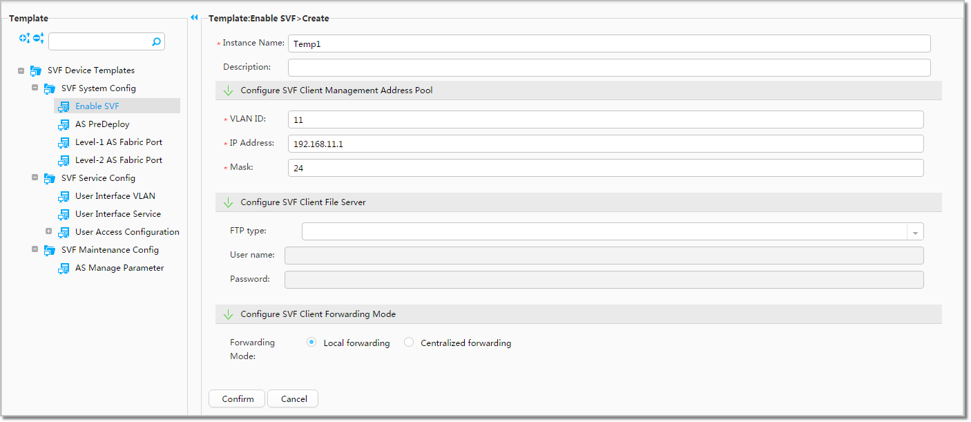
- Set Instance Name to Temp1, set VLAN ID, IP Address, and Mask in the Configure SVF Client Management Address Pool area to 11, 192.168.11.1, and 24 respectively, and click Confirm. The Enable SVF template is displayed on the page.
- Choose from the navigation tree, choose in Template, and click Create.
- Create a template instance and set AS access parameters.
- Choose from the navigation tree, choose in Template, and click Create.
- Set Instance Name to ASTemp and set other parameters as shown in the following figure.
- Choose from the navigation tree, choose in Template, and click Create.
- Create a template instance Level-1 AS Fabric Port.
- Choose from the navigation tree, choose in Template, and click Create.
- Set Instance Name to ParentToL1as, set other parameters as shown in the following figure, and click Confirm. The Level-1 AS Fabric Port template is displayed on the page.
- Choose from the navigation tree, choose in Template, and click Create.
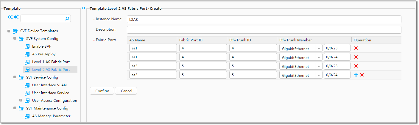
- Create a template instance Level-2 AS Fabric Port.
- Choose from the navigation tree, choose in Template, and click Create.
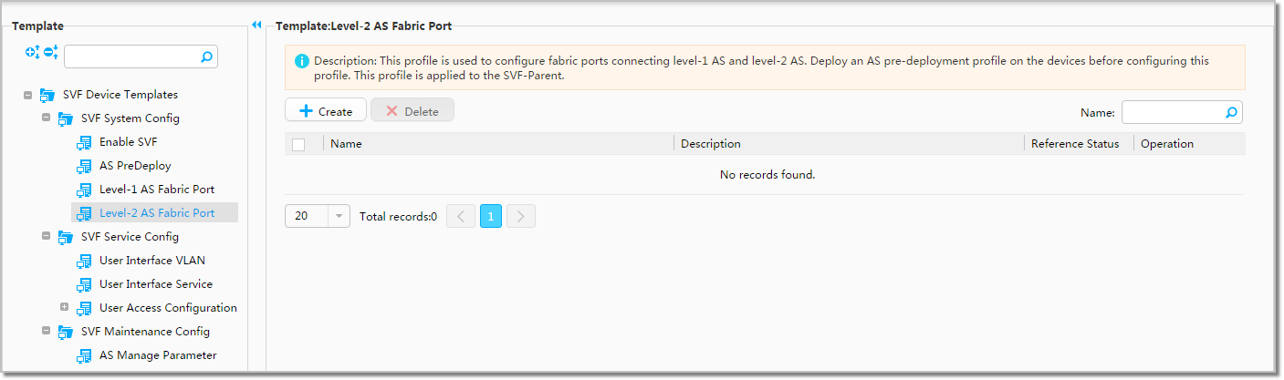
- Set Instance Name to L2AS, set other parameters as shown in the following figure, and click Confirm. The Level-2 AS Fabric Port template is displayed on the page.
- Choose from the navigation tree, choose in Template, and click Create.
- Deploy the template instances to the parent.
- Choose from the navigation tree. The default service configuration matrix is displayed.
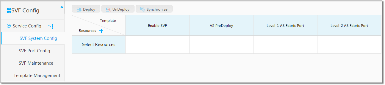
- Click
 next to Resources and select SVF-S12708 as the default SVF Parent.
 - In the service configuration matrix, place the mouse in each blank cell, click to select the created template instances one by one, and click Confirm.
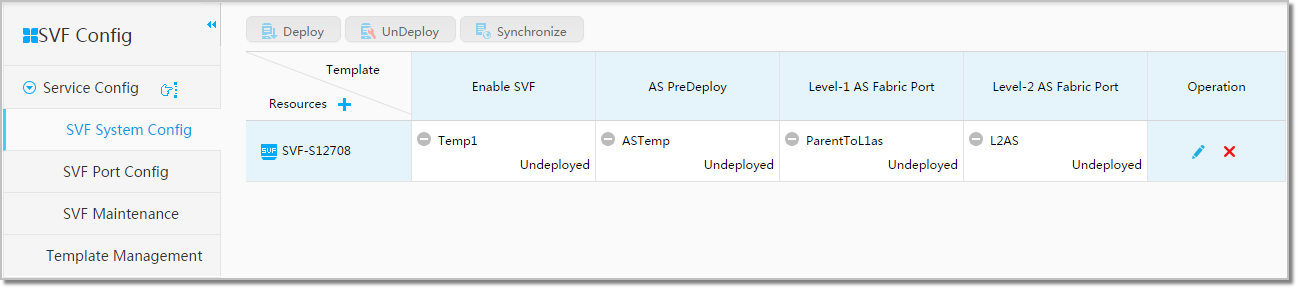
- In the system configuration matrix, place the mouse in the lower right corner of each cell with a template instance, and click
 to deploy the template instance to the parent.
- Choose from the navigation tree. The default service configuration matrix is displayed.
- After logging in to each AS through the CLI, you can run the reset saved-configuration command to delete the AS configuration and then run the reboot command to restart the AS. If a message is displayed asking whether you want to save the configuration, select N. And then connect the parent to level-1 ASs and level-1 ASs to level-2 ASs using cables.
- Create port groups.
- Choose from the main menu. Device resources on the entire network are displayed on the page.
- Click
 in the upper right corner of the page and set IP Address to 10.137.240.114. The SVF device with the specified IP address is displayed on the page.
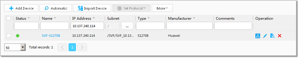
- Click the device name link in Name to access the NE Manager of the device.
- Choose from the navigation tree, and click Create Group.
- Set Group Name to PortGroup1, and click Confirm.
- Set Group Name to PortGroup2, and click Confirm.
- Enter as1 in the AS Name search box and click Search. Select all the ports of as1, click Add to Group, and select PortGroup1.
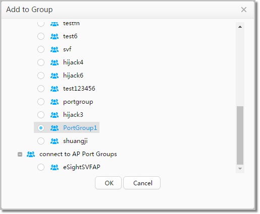
- Repeat the preceding step to add ports of as2 and as4 to PortGroup1, and ports of as3 and as5 to PortGroup2.
- Create user interface VLAN templates.
- Choose from the main menu.
- Choose from the navigation tree, choose in Template, and click Create.
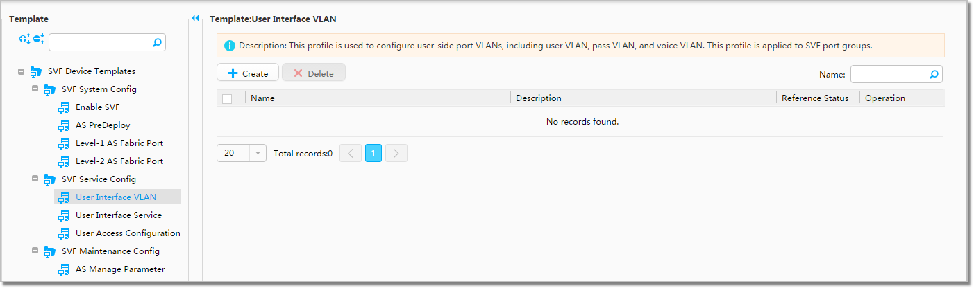
- Set Instance Name to VLAN10, set other parameters as shown in the following figure, and click Confirm. The user interface VLAN template VLAN10 is displayed on the page.
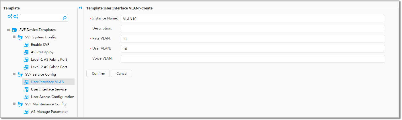
- Click Create, set Instance Name to VLAN20, set other parameters as shown in the following figure, and click Confirm. The user interface VLAN template VLAN20 is displayed on the page.

- Choose from the main menu.
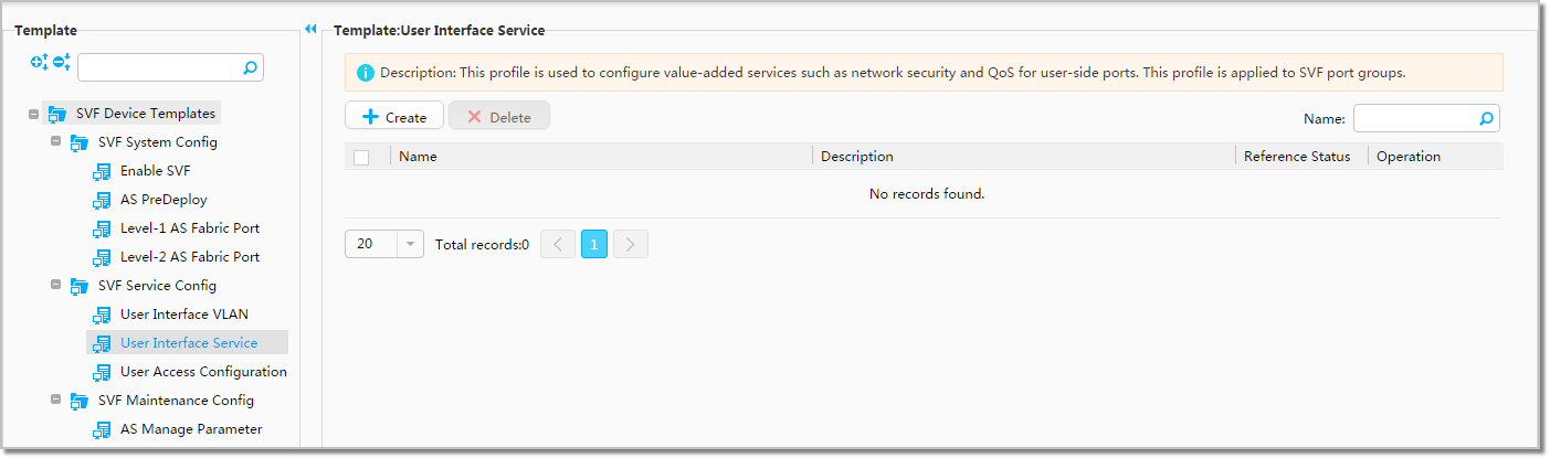
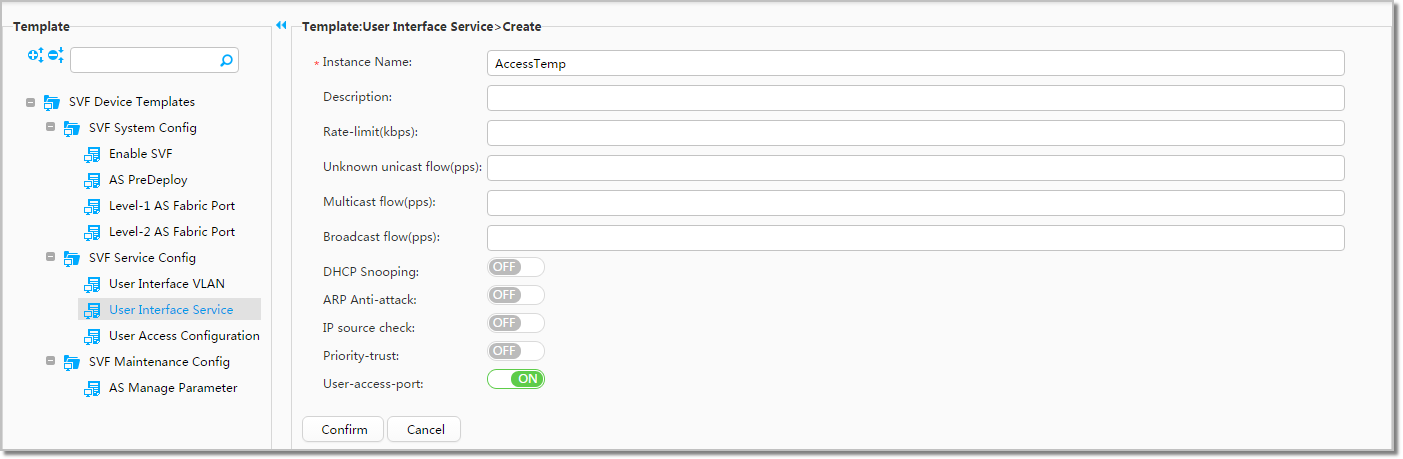
- Create a user interface service template.
- Choose from the navigation tree, choose in Template, and click Create.
- Set Instance Name to AccessTemp, set other parameters as shown in the following figure, and click Confirm. The user interface service template AccessTemp is displayed on the page.
- Deploy the SVF user interface VLAN and service templates to port groups.
- Choose from the navigation tree. The default service configuration matrix is displayed.
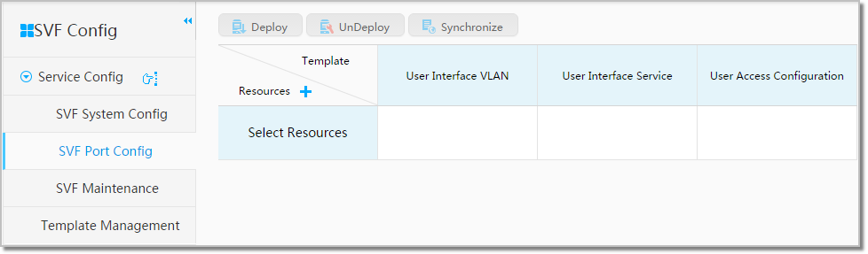
- Click next to Resources, select PortGroup1 and PortGroup2, and click Confirm.
- In the service configuration matrix, place the mouse in each blank cell, click to select the created template instances one by one, and click Confirm.
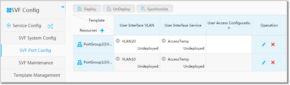
- In the service configuration matrix, place the mouse in the lower right corner of each cell with a template instance, and click to deploy the template instance to the port group.
- Choose from the navigation tree. The default service configuration matrix is displayed.
Result
After the SVF access layer configuration is complete, verify the configuration as follows:
- Choose from the main menu. The SVF topology
 is displayed. Double-click the icon to view the layout in the SVF system.
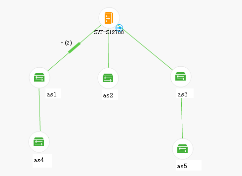
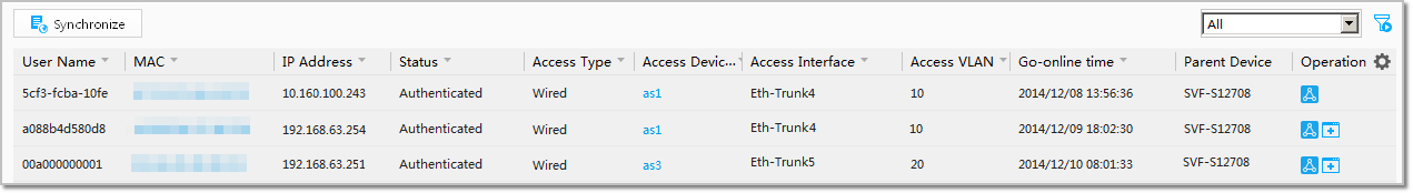
- Choose from the main menu. You can view the list of online users on the page that is displayed.