What Is an Optical Module
On an optical network, a sender needs to convert electrical signals into optical signals before sending them to a receiver, and the receiver needs to convert received optical signals into electrical signals. An optical module is a component that completes electrical/optical conversion on an optical network. Figure 1 shows the structure of an optical module.
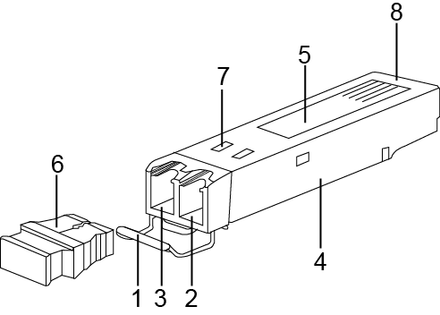
1. Handle |
2. Receiver |
3. Transmitter |
4. Shell |
5. Label |
6. Dust plug |
7. Spring |
8. Connector |
- |
Figure 2 shows an SFP/eSFP optical module.
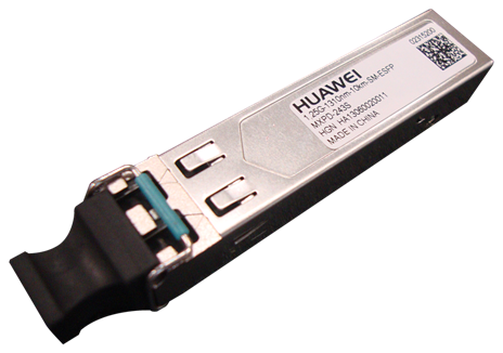
Figure 3 shows the appearance of an SFP+ optical module.
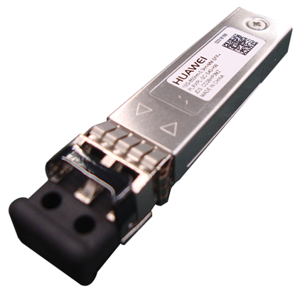
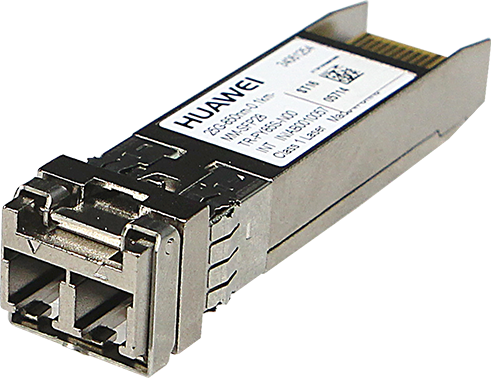
Figure 4 shows the appearance of a SFP28 optical module.
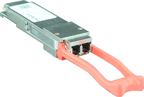
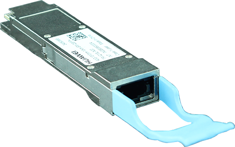

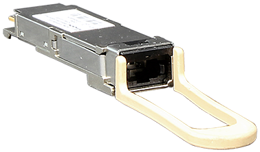
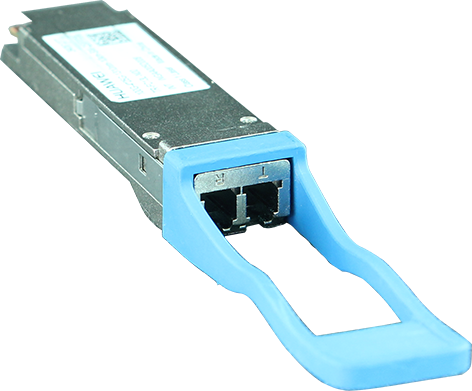
The side with an L-shaped notch close to the connector is the top of a QSFP+ optical module, as shown in Figure 5. When connecting a QSFP+ optical module to a port, keep the top side upward. Do not insert the QSFP+ optical module upside down.
Currently, there is no formal standard for 40G Ethernet. Therefore, a device may not display complete diagnostic information about 40GE optical modules. This is an acceptable fact in the telecommunications industry and does not affect functions of 40GE optical modules.
Figure 7 shows the appearance of a CSFP optical module.
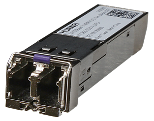
Figure 8 shows the appearance of an XFP module.
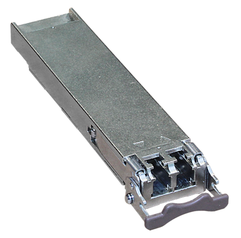

The SFP+ and XFP optical modules are 10GE hot-pluggable optical modules. Compared with the SFP+ optical modules, the XFP optical modules have a larger caliber.
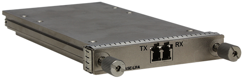
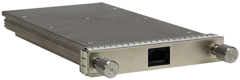
Figure 9 and Figure 10 show CFP optical modules for different optical fibers.