Installing a Chassis in Cabinet
Precautions
Ensure that the cabinet has been properly installed before installing devices in the cabinet. The cabinet can be installed on an ESD floor or concrete floor.

- When installing devices, ensure that the total heat consumption of all devices in the cabinet is less than or equal to the heat dissipation capability of the cabinet.
- To prevent heat dissipation from being affected by air return, devices must be installed at an interval of 1 U or more in the cabinet. In addition, the middle-column cabinets support device stacking.
- Ensure that heat dissipation holes on the panel are not blocked.
- When the chassis is installed together with other equipment in the same cabinet, do not install the chassis near the air exhaust vent of other equipment.
- Determine whether the air exhaust vent affects adjacent devices to avoid high temperature of adjacent devices.
Installing a Chassis in a Standard 19-Inch Cabinet
- Wear an ESD wrist strap or ESD gloves. Ensure that the ESD wrist strap is grounded and in close contact with your wrist.
- Use a measuring tape to measure the distance between the front and rear mounting rails in the cabinet.
- Select front mounting brackets, rear mounting brackets, and rear mounting bracket guide rails according to the distance between the front and rear mounting rails. Table 1 shows the front mounting brackets, rear mounting brackets, and rear mounting bracket guide rails used on the device for different distances between the front and rear mounting rails.
Table 1 Selection of front mounting brackets, rear mounting brackets, and rear mounting bracket guide rails used on the device Distance Between Front and Rear Mounting Rails
Front Mounting Brackets, Rear Mounting Brackets, and Rear Mounting Bracket Guide Rails
310 mm to 351 mm

369 mm to 410 mm
438 mm to 479 mm
497 mm to 538 mm
539 mm to 637 mm

638 mm to 696 mm

697 mm to 835 mm
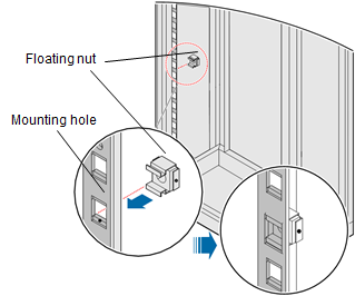
- Fix floating nuts and M6 screws in the correct holes.

When tightening floating nuts, ensure a minimum distance of 75 mm between a chassis side and its adjacent column for ventilation.
- Use a torque screwdriver to install the front mounting brackets using three M4 screws with a torque of 1.2 N m.
- Use a torque screwdriver to install the extension rails of the expandable mounting brackets on the rear of the chassis using four M4 screws with a torque of 1.2 N m.

Install the front mounting brackets, rear mounting brackets, and rear mounting bracket guide rails depending on the distance between the front and rear mounting rails in the cabinet. See Table 2.
Table 2 Installing front mounting brackets, rear mounting brackets, and rear mounting bracket guide rails Distance Between Front and Rear Mounting Rails
Installation of Front Mounting Brackets, Rear Mounting Brackets, and Rear Mounting Bracket Guide Rails
310 mm to 351 mm

369 mm to 410 mm

438 mm to 479 mm

497 mm to 538 mm

539 mm to 637 mm

638 mm to 696 mm

697 mm to 835 mm

- Use a torque screwdriver to install the extension runners of the expandable mounting brackets on the rear posts of the cabinet using M6 screws with a torque of 3 N m. Horizontally insert the chassis into the cabinet from the front of the cabinet until the extension rails are fully inserted into the extension runners. Then, use screws to fix the front mounting brackets to the cabinet.
- Use a torque screwdriver to install the ground cable using an M4 screw with a torque of 1.2 N m.