Assembling an SPC1 Connector and the Power Cable
Context

Colors and exteriors of cables may vary with countries and regions.
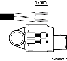
Figure1shows an SPC1 connector.
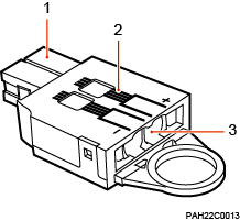
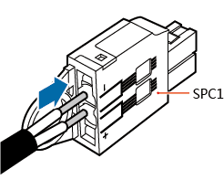
(1) SPC1 |
(2) Scale |
(3) Hole for the cable |
Procedure
- Strip the jacket off the cable according to the scale on the connector, as shown in Figure2.

- The figure for stripping the jacket shows the minimum length of the jacket to be stripped off the cable.
- Ensure that the wires do not split during cable stripping.
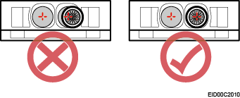
- Insert the positive conducting wire to hole 1 (+) and the negative conducting wire to hole 2 (–), as shown in Figure3.
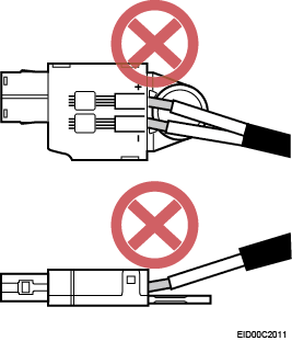
- Before power-on, check whether the positive and negative conducting wires of all power cables are correctly connected. Any incorrect power cable connection may cause damage to equipment or unexpected injuries of human body.
- If the conducting wires are inserted properly, you will hear two click sounds.
- When a cable is connected to an SPC1 connector, if the connector is not removed and the cable is reversely connected, the following issues may occur: sparking, fuse blowout, and connector damage. Therefore, remove the SPC1 connector before the cable connection.
The cross-sectional area of the cable supported by the SPC1 connector ranges from 1.5 mm2 to 10 mm2 or 0.0023 in.2 to 0.016 in.2.
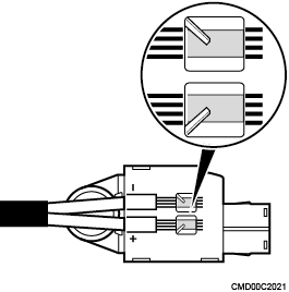
- After the conducting wires are inserted, check whether they are secured by springs from the visible window, as shown in Figure4. Pull each conducting wire slightly to check whether it is securely connected. If the conducting wire is pulled out a bit or a spring presses the insulation layer, remove and cut the split conducting wire, and then strip the jacket and install the conducting wire again.