Example for Configuring IPoE User Access When L3VPN Services Are Carried Through SRv6 BE
This section provides an example for configuring IPoE user access through binding authentication when L3VPN services are carried through SRv6 BE.
Networking Requirements
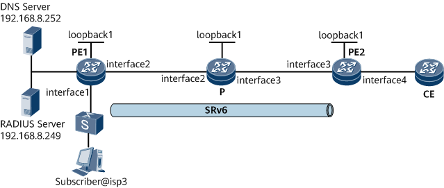
As shown in Figure 1, a user belongs to domain isp3 and accesses the Internet through GE0/1/1 on PE1 in common IPoE mode. PE1, the P, and PE2 belong to IS-IS process 1 and are all Level-1 devices. PE1 functions as a BRAS and uses the RADIUS authentication and accounting modes. PE1, the P, and PE2 belong to the same AS and are interconnected over an IPv6 network through IS-IS. A bidirectional SRv6 BE path is established between PE1 and PE2 to carry L3VPNv4 services.

In this example, interface1, interface2, interface3, and interface4 represent GE0/1/1, GE0/1/2, GE0/1/3, and GE0/1/4, respectively.
Device |
Interface |
IP Address |
|---|---|---|
|
PE1 |
GE0/1/1 |
2001:db8:100::1/96 |
GE0/1/2 |
2001:db8:10::1/96 |
|
Loopback1 |
2001:db8:1::1/64 |
|
|
P |
GE0/1/2 |
2001:db8:10::2/96 |
GE0/1/3 |
2001:db8:20::2/96 |
|
Loopback1 |
2001:db8:2::2/64 |
|
|
PE2 |
GE0/1/3 |
2001:db8:20::1/96 |
GE0/1/4 |
10.2.1.1/24 |
|
Loopback1 |
2001:db8:3::3/64 |
Configuration Roadmap
The configuration roadmap is as follows:
- Enable the IPv6 forwarding capability on each interface of PE1, the P, and PE2. Configure IPv6 addresses for each interface and the loopback interface of the control channel.
- Configure AAA schemes on PE1.
- Configure a RADIUS server group.
- Configure an address pool.
- Configure a user group.
- Configure an authentication domain.
- Configure a BAS interface.
- Enable IS-IS, configure an IS-IS level, and specify a network entity on PE1, the P, and PE2.
- Configure VPN instances on PE1 and PE2.
- Establish an MP-IBGP peer relationship between PE1 and PE2.
- Establish an SRv6 BE path between PE1 and PE2.
- Configure a traffic policy to identify SRv6 users.
Data Preparation
To complete the configuration, you need the following data:
- Authentication scheme name and authentication mode
- Accounting scheme name and accounting mode
- RADIUS server group name, and IP addresses and port numbers of the RADIUS authentication and accounting servers
- IP address pool name, gateway address, and DNS server address
- Domain name
- PE1 interface parameters
- IPv6 addresses of each interface on PE1, the P, and PE2
- IS-IS process ID for PE1, the P, and PE2
- IS-IS level for PE1, the P, and PE2
- VPN instance names, RDs, and RTs on PE1 and PE2
Procedure
- Enable the IPv6 forwarding capability on each interface. Configure IPv6 addresses for each interface and the loopback interface of the control channel.
# Configure PE1. The configurations of the P and PE2 are similar to the configuration of PE1. For configuration details, see "Configuration Files" in this section.
<HUAWEI> system-view
[~HUAWEI] sysname PE1
[*HUAWEI] commit
[~PE1] interface gigabitethernet 0/1/2
[~PE1-GigabitEthernet0/1/2] ipv6 enable
[*PE1-GigabitEthernet0/1/2] ipv6 address 2001:DB8:10::1 96
[*PE1-GigabitEthernet0/1/2] quit
[*PE1] interface LoopBack 1
[*PE1-LoopBack1] ipv6 enable
[*PE1-LoopBack1] ipv6 address 2001:DB8:1::1 64
[*PE1-LoopBack1] quit
[*PE1] commit
- Configure AAA schemes on PE1.
# Configure an authentication scheme.
[~PE1] aaa
[*PE1-aaa] authentication-scheme auth3
[*PE1-aaa-authen-auth3] authentication-mode radius
[*PE1-aaa-authen-auth3] commit
[~PE1-aaa-authen-auth3] quit
# Configure an accounting scheme.
[~PE1-aaa] accounting-scheme acct3
[*PE1-aaa-accounting-acct3] accounting-mode radius
[*PE1-aaa-accounting-acct3] commit
[~PE1-aaa-accounting-acct3] quit
[~PE1-aaa] quit
- Configure a RADIUS server group.
[~PE1] radius-server group rd3
[*PE1-radius-rd3] radius-server authentication 192.168.8.249 1812
[*PE1-radius-rd3] radius-server accounting 192.168.8.249 1813
[*PE1-radius-rd3] commit
[~PE1-radius-rd3] radius-server type standard
[*PE1-radius-rd3] radius-server shared-key-cipher it-is-my-secret1
[*PE1-radius-rd3] commit
[~PE1-radius-rd3] quit
- Configure an address pool.
[~PE1] ip pool pool3 bas local [*PE1-ip-pool-pool3] gateway 10.82.2.1 255.255.255.0 [*PE1-ip-pool-pool3] commit [~PE1-ip-pool-pool3] section 0 10.82.2.2 10.82.2.200 [~PE1-ip-pool-pool3] dns-server 192.168.8.252 [*PE1-ip-pool-pool3] commit [~PE1-ip-pool-pool3] vpn-instance vpna [~PE1-ip-pool-pool3] quit - Configure a user group.
[~PE1] user-group srv6
- Configure an authentication domain.
[~PE1] aaa
[~PE1-aaa] domain isp3
[*PE1-aaa-domain-isp3] authentication-scheme auth3
[*PE1-aaa-domain-isp3] accounting-scheme acct3
[*PE1-aaa-domain-isp3] radius-server group rd3
[*PE1-aaa-domain-isp3] user-group srv6
[*PE1-aaa-domain-isp3] commit
[~PE1-aaa-domain-isp3] ip-pool pool3
[~PE1-aaa-domain-isp3] vpn-instance vpna
[~PE1-aaa-domain-isp3] quit
[~PE1-aaa] quit
- Configure a BAS interface.
[~PE1] interface GigabitEthernet 0/1/1
[~PE1-GigabitEthernet0/1/1] bas
[~PE1-GigabitEthernet0/1/1-bas] access-type layer2-subscriber
[*PE1-GigabitEthernet0/1/1-bas] authentication-method bind
[*PE1-GigabitEthernet0/1/1-bas] default-domain authentication isp3
[*PE1-GigabitEthernet0/1/1-bas] commit
[~PE1-GigabitEthernet0/1/1-bas] quit
[~PE1-GigabitEthernet0/1/1] quit
- Configure IS-IS.# Configure PE1.
[~PE1] interface gigabitethernet 0/1/2
[~PE1-GigabitEthernet0/1/2] ipv6 enable
[*PE1-GigabitEthernet0/1/2] ipv6 address 2001:DB8:10::1 96
[*PE1-GigabitEthernet0/1/2] quit
[*PE1] interface LoopBack 1
[*PE1-LoopBack1] ipv6 enable
[*PE1-LoopBack1] ipv6 address 2001:DB8:1::1 64
[*PE1-LoopBack1] quit
[*PE1] commit
# Configure the P.[~P] isis 1 [*P-isis-1] is-level level-1 [*P-isis-1] cost-style wide [*P-isis-1] network-entity 10.0000.0000.0002.00 [*P-isis-1] ipv6 enable topology ipv6 [*P-isis-1] quit [*P] interface gigabitethernet 0/1/2 [*P-GigabitEthernet0/1/2] isis ipv6 enable 1 [*P-GigabitEthernet0/1/2] quit [*P] interface gigabitethernet 0/1/3 [*P-GigabitEthernet0/1/3] isis ipv6 enable 1 [*P-GigabitEthernet0/1/3] quit [*P] interface loopback1 [*P-LoopBack1] isis ipv6 enable 1 [*P-LoopBack1] quit [*P] commit
# Configure PE2.[~PE2] isis 1 [*PE2-isis-1] is-level level-1 [*PE2-isis-1] cost-style wide [*PE2-isis-1] network-entity 10.0000.0000.0003.00 [*PE2-isis-1] ipv6 enable topology ipv6 [*PE2-isis-1] quit [*PE2] interface gigabitethernet 0/1/3 [*PE2-GigabitEthernet0/1/3] isis ipv6 enable 1 [*PE2-GigabitEthernet0/1/3] quit [*PE2] interface loopback1 [*PE2-LoopBack1] isis ipv6 enable 1 [*PE2-LoopBack1] quit [*PE2] commit
After completing the configuration, perform the following operations to check whether IS-IS is successfully configured:
# Display information about the IS-IS neighbor. The following example uses the command output on PE1.
[~PE1] display isis peer
Peer information for ISIS(1)

System Id        Interface        Circuit Id         State HoldTime Type      PRI
----------------------------------------------------------------------------------
0000.0000.0002*  GE0/1/2          0000.0000.0002.01  Up    8s       L1        64

Total Peer(s): 1
# Display information about the IS-IS routing table. The following example uses the command output on PE1.
[~PE1] display isis route Route information for ISIS(1) ----------------------------- ISIS(1) Level-1 Forwarding Table -------------------------------- IPV6 Dest. ExitInterface NextHop Cost Flags --------------------------------------------------------------------------------------------- 2001:DB8:1::1/64 Loop1 Direct 0 D/-/L/- 2001:DB8:20::/96 GE0/1/2 FE80::3A92:6CFF:FE21:10 20 A/-/-/- 2001:DB8:3::3/64 GE0/1/2 FE80::3A92:6CFF:FE21:10 20 A/-/-/- 2001:DB8:10::/96 GE0/1/2 Direct 10 D/-/L/- 2001:DB8:20::/96 GE0/1/2 FE80::3A92:6CFF:FE21:10 20 A/-/-/- Flags: D-Direct, A-Added to URT, L-Advertised in LSPs, S-IGP Shortcut, U-Up/Down Bit Set, LP-Local Prefix-Sid Protect Type: L-Link Protect, N-Node Protect - Configure a VPN instance enabled with the IPv4 address family on PE1 and PE2.
# Configure PE1.
[~PE1] ip vpn-instance vpna
[*PE1-vpn-instance-vpna] ipv4-family
[*PE1-vpn-instance-vpna-af-ipv4] route-distinguisher 100:1
[*PE1-vpn-instance-vpna-af-ipv4] vpn-target 111:1 both
[*PE1-vpn-instance-vpna-af-ipv4] commit
[~PE1-vpn-instance-vpna-af-ipv4] quit
[~PE1-vpn-instance-vpna] quit
# Configure PE2.
[~PE2] ip vpn-instance vpna
[*PE2-vpn-instance-vpna] ipv4-family
[*PE2-vpn-instance-vpna-af-ipv4] route-distinguisher 200:1
[*PE2-vpn-instance-vpna-af-ipv4] vpn-target 111:1 both
[*PE2-vpn-instance-vpna-af-ipv4] commit
[~PE2-vpn-instance-vpna-af-ipv4] quit
[~PE2-vpn-instance-vpna] quit
- Establish an MP-IBGP peer relationship between PE1 and PE2.
# Configure PE1.
[~PE1] bgp 100
[~PE1-bgp] peer 2001:DB8:3::3 as-number 100
[*PE1-bgp] peer 2001:DB8:3::3 connect-interface loopback 1
[*PE1-bgp] ipv4-family vpnv4
[*PE1-bgp-af-vpnv4] peer 2001:DB8:3::3 enable
[*PE1-bgp-af-vpnv4] commit
[~PE1-bgp-af-vpnv4] quit
[~PE1-bgp] quit
# Configure PE2.
[~PE2] bgp 100
[~PE2-bgp] peer 2001:DB8:1::1 as-number 100
[*PE2-bgp] peer 2001:DB8:1::1 connect-interface loopback 1
[*PE2-bgp] ipv4-family vpnv4
[*PE2-bgp-af-vpnv4] peer 2001:DB8:1::1 enable
[*PE2-bgp-af-vpnv4] commit
[~PE2-bgp-af-vpnv4] quit
[~PE2-bgp] quit
After completing the configuration, run the display bgp vpnv4 all peer command on PE1. The command output shows that BGP peer relationship has been established between the PEs and is in the Established state.
The following example uses the command output on PE1.
[~PE1] display bgp vpnv4 all peer BGP local router ID : 1.1.1.1 Local AS number : 100 Total number of peers : 1 Peers in established state : 1 Peer V AS MsgRcvd MsgSent OutQ Up/Down State PrefRcv 2001:DB8:3::3 4 100 216 220 0 03:03:35 Established 2 - Establish an SRv6 BE path between PE1 and PE2.
An End.DT4 SID can be either dynamically allocated through BGP or manually configured. If a dynamically allocated SID and a manually configured SID both exist, the latter takes effect. If you have run the segment-routing ipv6 locator locator-name command to enable BGP to dynamically allocate End.DT4 SIDs, you do not need to run the opcode func-opcode end-dt4 vpn-instance vpn-instance-name command to configure the static SID opcode.
In this example, dynamic allocation through BGP is used.
# Configure PE1.
[~PE1] segment-routing ipv6
[*PE1-segment-routing-ipv6] encapsulation source-address 2001:DB8:1::1
[*PE1-segment-routing-ipv6] locator as1 ipv6-prefix 2001:DB8:100:: 64 static 32
[*PE1-segment-routing-ipv6-locator] quit
[*PE1-segment-routing-ipv6] quit
[*PE1] bgp 100
[*PE1-bgp] ipv4-family vpnv4
[*PE1-bgp-af-vpnv4] peer 2001:DB8:3::3 prefix-sid
[*PE1-bgp-af-vpnv4] quit
[*PE1-bgp] ipv4-family vpn-instance vpna
[*PE1-bgp-vpna] segment-routing ipv6 best-effort
[*PE1-bgp-vpna] segment-routing ipv6 locator as1
[*PE1-bgp-vpna] commit
[~PE1-bgp-vpna] quit
[~PE1-bgp] quit
[~PE1] isis 1
[~PE1-isis-1] segment-routing ipv6 locator as1
[*PE1-isis-1] commit
[~PE1-isis-1] quit
# Configure PE2.
[~PE2] segment-routing ipv6
[*PE2-segment-routing-ipv6] encapsulation source-address 2001:DB8:3::3
[*PE2-segment-routing-ipv6] locator as1 ipv6-prefix 2001:DB8:300:: 64 static 32
[*PE2-segment-routing-ipv6-locator] quit
[*PE2-segment-routing-ipv6] quit
[*PE2] bgp 100
[*PE2-bgp] ipv4-family vpnv4
[*PE2-bgp-af-vpnv4] peer 2001:DB8:1::1 prefix-sid
[*PE2-bgp-af-vpnv4] quit
[*PE2-bgp] ipv4-family vpn-instance vpna
[*PE2-bgp-vpna] segment-routing ipv6 best-effort
[*PE2-bgp-vpna] segment-routing ipv6 locator as1
[*PE2-bgp-vpna] commit
[~PE2-bgp-vpna] quit
[~PE2-bgp] quit
[~PE2] isis 1
[~PE2-isis-1] segment-routing ipv6 locator as1
[*PE2-isis-1] commit
[~PE2-isis-1] quit
- Configure a traffic policy to identify SRv6 users.
[~PE1] acl number 6000
[*PE1-acl-ucl-6000] rule 1 permit ip source user-group srv6
[*PE1-acl-ucl-6000] commit
[~PE1-acl-ucl-6000] quit
[~PE1] traffic classifier srv6
[*PE1-classifier-srv6] if-match acl 6000
[*PE1-classifier-srv6] commit
[~PE1-classifier-srv6] quit
[~PE1] traffic behavior srv6
[*PE1-behavior-srv6] redirect ip-nexthop 10.2.1.2
[*PE1- behavior-srv6] commit
[~PE1- behavior-srv6] quit
[~PE1] traffic policy srv6
[*PE1-trafficpolicy-srv6] classifier srv6 behavior srv6
[*PE1-trafficpolicy-srv6] commit
[~PE1-trafficpolicy-srv6] quit
[~PE1] traffic-policy srv6 inbound
[*PE1] commit
After an ACL policy is configured, user traffic from the user group named srv6 will be imported to the SRv6 BE path. To prevent user traffic from entering the SRv6 BE path, run the reauthorize command to modify the user group or use the RADIUS attribute to modify the user group so that traffic is forwarded over a non-SRv6 BE path.
- Verify the configuration.Run the display segment-routing ipv6 locator [ locator-name ] verbose command to check SRv6 locator information. The following example uses the command output on PE1.
[~PE1] display segment-routing ipv6 locator verbose
                        Locator Configuration Table
                        ---------------------------

LocatorName  : as1                                       LocatorID   : 1
IPv6Prefix   : 2001:DB8:100::                            PrefixLength: 64
StaticLength : 32                                        Reference   : 2
ArgsLength   : 0
AutoSIDPoolID: 8193
AutoSIDBegin : 2001:DB8:100::1:0:0
AutoSIDEnd   : 2001:DB8:100::FFFF:FFFF:FFFF:FFFF

Total Locator(s): 1
Run the display segment-routing ipv6 local-sid end-dt4 forwarding command to check information about the SRv6 local SID table. The following example uses the command output on PE1.[~PE1] display segment-routing ipv6 local-sid end-dt4 forwarding My Local-SID End.DT4 Forwarding Table ------------------------------------- SID : 2001:DB8:100::1:0:0/128 FuncType : End.DT4 VPN Name : vpna VPN ID : 3 LocatorName: as1 LocatorID: 1 Total SID(s): 1Run the display bgp vpnv4 all routing-table command on PE1 and PE2 to check the BGP VPNv4 routing information. The following example uses the command output on PE1.[~PE1] display bgp vpnv4 all routing-table BGP Local router ID is 1.1.1.1 Status codes: * - valid, > - best, d - damped, x - best external, a - add path, h - history, i - internal, s - suppressed, S - Stale Origin : i - IGP, e - EGP, ? - incomplete RPKI validation codes: V - valid, I - invalid, N - not-found Total number of routes from all PE: 2 Route Distinguisher: 100:1 Network NextHop MED LocPrf PrefVal Path/Ogn *> 127.0.0.0/8 0.0.0.0 0 0 ? Route Distinguisher: 200:1 Network NextHop MED LocPrf PrefVal Path/Ogn *>i 10.2.1.0/24 2001:DB8:3::3 0 100 0 ? VPN-Instance vpna, Router ID 1.1.1.1: Total Number of Routes: 2 Network NextHop MED LocPrf PrefVal Path/Ogn *>i 10.2.1.0/24 2001:DB8:3::3 0 100 0 ? *> 127.0.0.0/8 0.0.0.0 0 0 ?Run the display ip routing-table vpn-instance vpna command on PE1 and PE2 to check the routing table information about the VPN instance. The following example uses the command output on PE1.[~PE1] display ip routing-table vpn-instance vpna Route Flags: R - relay, D - download to fib, T - to vpn-instance, B - black hole route ------------------------------------------------------------------------------ Routing Table : vpna Destinations : 8 Routes : 8 Destination/Mask Proto Pre Cost Flags NextHop Interface 10.2.1.0/24 IBGP 255 0 RD 2001:DB8:300::1:0:3C SRv6 BE 127.0.0.0/8 Direct 0 0 D 127.0.0.1 InLoopBack0 255.255.255.255/32 Direct 0 0 D 127.0.0.1 InLoopBack0
Configuration Files
- PE1 configuration file
#
sysname PE1
#
ip vpn-instance vpna
 ipv4-family
  route-distinguisher 100:1
  tnl-policy p1
  vpn-target 111:1 export-extcommunity
  vpn-target 111:1 import-extcommunity
#
radius-server group rd3
 radius-server shared-key-cipher %^%#vS%796FO7%C~pB%CR=q;j}gSCqR-X6+P!.DYI@)%^%#
 radius-server authentication 192.168.8.249 1812 weight 0
 radius-server accounting 192.168.8.249 1813 weight 0
#
ip pool pool3 bas local
 vpn-instance vpna
 gateway 10.82.2.1 255.255.255.0
 section 0 10.82.2.2 10.82.2.200
 dns-server 192.168.8.252
#
acl number 6000
 rule 1 permit ip source user-group srv6
#
traffic classifier srv6 operator or
 if-match acl 6000 precedence 1
#
traffic behavior srv6
 redirect ip-nexthop 10.2.1.2
#
traffic policy srv6
 share-mode
 classifier srv6 behavior srv6 precedence 1
#
aaa
 #
 authentication-scheme auth3
 #
 accounting-scheme acct3
 #
 domain isp3
  authentication-scheme auth3
  accounting-scheme acct3
  radius-server group rd3
  ip-pool pool3
  vpn-instance vpna
#
segment-routing ipv6
 encapsulation source-address 2001:DB8:1::1
 locator as1 ipv6-prefix 2001:DB8:100:: 64 static 32
#
isis 1
 is-level level-1
 cost-style wide
 network-entity 10.0000.0000.0001.00
 #
 ipv6 enable topology ipv6
 segment-routing ipv6 locator as1
 #
#
interface GigabitEthernet0/1/1
 bas
 #
  access-type layer2-subscriber default-domain authentication isp3
  authentication-method bind
 #
#
interface GigabitEthernet0/1/2
 undo shutdown
 ipv6 enable
 ipv6 address 2001:DB8:10::1/96
 isis ipv6 enable 1
#
interface GigabitEthernet1/0/5
 undo shutdown
 ip address 192.168.8.1 24
#
interface LoopBack1
 ipv6 enable
 ipv6 address 2001:DB8:1::1/64
 isis ipv6 enable 1
#
bgp 100
 router-id 1.1.1.1
 peer 2001:DB8:3::3 as-number 100
 peer 2001:DB8:3::3 connect-interface LoopBack1
 #
 ipv4-family unicast
  undo synchronization
 #
 ipv6-family unicast
  undo synchronization
 #
 ipv4-family vpnv4
  policy vpn-target
  peer 2001:DB8:3::3 enable
  peer 2001:DB8:3::3 prefix-sid
 #
 ipv4-family vpn-instance vpna
  import-route direct
  segment-routing ipv6 locator as1
  segment-routing ipv6 best-effort
#
route-policy p1 permit node 10
 apply extcommunity color 0:101
#
traffic-policy srv6 inbound
#
tunnel-policy p1
 tunnel select-seq ipv6 srv6-te-policy load-balance-number 1
#
return
- P configuration file
#
sysname P
#
isis 1
 is-level level-1
 cost-style wide
 network-entity 10.0000.0000.0002.00
 #
 ipv6 enable topology ipv6
 #
#
interface GigabitEthernet0/1/2
 undo shutdown
 ipv6 enable
 ipv6 address 2001:DB8:10::2/96
 isis ipv6 enable 1
#
interface GigabitEthernet0/1/3
 undo shutdown
 ipv6 enable
 ipv6 address 2001:DB8:20::1/96
 isis ipv6 enable 1
#
interface LoopBack1
 ipv6 enable
 ipv6 address 2001:DB8:2::2/64
 isis ipv6 enable 1
#
return
- PE2 configuration file
#
sysname PE2
#
ip vpn-instance vpna
 ipv4-family
  route-distinguisher 200:1
  vpn-target 111:1 export-extcommunity
  vpn-target 111:1 import-extcommunity
#
segment-routing ipv6
 encapsulation source-address 2001:DB8:3::3
 locator as1 ipv6-prefix 2001:DB8:300:: 64 static 32
#
isis 1
 is-level level-1
 cost-style wide
 network-entity 10.0000.0000.0003.00
 #
 ipv6 enable topology ipv6
 segment-routing ipv6 locator as1
 #
#
interface GigabitEthernet0/1/3
 undo shutdown
 ipv6 enable
 ipv6 address 2001:DB8:20::2/96
 isis ipv6 enable 1
#
interface GigabitEthernet0/1/4
 undo shutdown
 ip binding vpn-instance vpna
 ip address 10.2.1.1 255.255.255.0
#
interface LoopBack1
 ipv6 enable
 ipv6 address 2001:DB8:3::3/64
 isis ipv6 enable 1
#
bgp 100
 router-id 2.2.2.2
 peer 2001:DB8:1::1 as-number 100
 peer 2001:DB8:1::1 connect-interface LoopBack1
 #
 ipv4-family unicast
  undo synchronization
 #
 ipv6-family unicast
  undo synchronization
 #
 ipv4-family vpnv4
  policy vpn-target
  peer 2001:DB8:1::1 enable
  peer 2001:DB8:1::1 prefix-sid
 #
 ipv4-family vpn-instance vpna
  import-route direct
  segment-routing ipv6 locator as1
  segment-routing ipv6 best-effort
#
return