Diameter
Introduction to Diameter
The Diameter protocol was proposed by the Authentication, Authorization and Accounting (AAA) workgroup of Internet Engineering Task Force (IETF) as the next-generation IP-based AAA protocol. The Diameter protocol is evolved from the Remote Authentication Dial In User Service (RADIUS) protocol.
As 3rd Generation (3G) networks are evolving to all-IP networks, IP-capable network entities are used on core networks, IP-based technologies are used on access networks, and mobile terminals can be activated as IP clients. Therefore, Diameter, as a new AAA protocol, is introduced to the 3rd Generation Partnership Project (3GPP).
Diameter has the following functions:
- Authentication: authenticates users before the users use network resources.
- Authorization: authorizes users to access network resources.
- Accounting: collects and records information about network resource usage for billing or auditing. For example, Internet service providers (ISPs) can accurately record information about network resources used by users based on traffic or time.
Advantages
Diameter has the following advantages compared with RADIUS:
- Failover and failback mechanisms
- A better mechanism for handling packet loss, requiring the confirmation of each message
- Ensured data integrity and security
- End-to-end security provided by the Transport Layer Security (TLS)
- Capability negotiation
Diameter Header Format
A Diameter packet consists of the basic protocol information and application information. Figure 1 shows the format of a Diameter packet where Application-ID and AVPs are application information and other fields are basic protocol information.
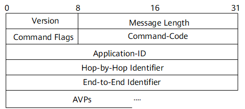
The fields are described as follows:
- Version: 1 byte. This field must be set to 1 to indicate Diameter Version 1.
- Message Length: 3 bytes. This field indicates the length of a Diameter message, including the header fields.
Command Flags: 1 byte. This field indicates the message type.
The following bits are assigned:
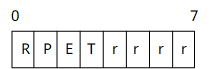
- R (Request): indicates whether the message is a request or an answer message. 1 indicates that the message is a request, and 0 indicates that the message is an answer.
- P (Proxiable): indicates whether the message can be forwarded. 1 indicates that the message can be proxied, relayed, or redirected. 0 indicates that the message must be locally processed.
- E (Error): indicates whether the message contains a protocol error. 1 indicates that the message contains a protocol error and that the message does not conform to the Augmented Backus-Naur Form (ABNF). Messages with the "E" bit set are commonly referred to as error messages.
- T (Potentially re-transmitted message): indicates whether the message is a duplicate request. This flag is set after a link failover to aid the removal of duplicate requests, or when resending requests are not yet acknowledged to indicate a possible duplicate request due to a link failure. The sender must clear this bit when sending a request for the first time, or set this bit for all other scenarios. Diameter agents are concerned only about the number of requests they send based on a single received request; retransmissions by other entities are not tracked. Diameter agents that receive a request with the T flag set must keep the T flag set in the forwarded request. This flag must not be set if an error answer message, such as a protocol error, has been received for the earlier request message. It can be set only when no answer has been received from the server for a request and the request is sent again. This flag must not be set in answer messages.
- r (Reserved): These flag bits are reserved for future use. They must be set to zero and ignored by the receiver.
- Command-Code: 3 bytes. This field indicates the command associated with the message. The Command-Code field in an answer message must contain the same value that was found in the corresponding request message.
Application-ID: 4 bytes. This field is used to identify the application to which a message applies. For example, the application can be an authentication application. The Application-ID field in the header must be the same as that contained in any relevant attribute-value pairs (AVPs) contained in the message.
For example, the Application IDs defined in Diameter are as follows:
- 0x00000000: indicates a Diameter Common Messages.
- 0x00000001: indicates a Network Access Server Requirements.
- 0x00000003: indicates a Diameter Base Accounting.
- 0x00000004: indicates a Diameter Credit Control Application.
- 0x01000016: indicates a Diameter Policy Interface (Gx).
- Hop-by-Hop Identifier: 4 bytes. This field helps requests and replies. The sender must ensure that the Hop-by-Hop identifier in a request message is unique on a given connection at any given time and that the number is unique across reboots. The sender of an answer message must ensure that the Hop-by-Hop Identifier field contains the same value as that in the corresponding request message.
- End-to-End Identifier: 4 bytes. This field is used to detect duplicate messages.
- AVPs: Diameter attributes. A Diameter message consists of a Diameter header and AVPs. An AVP carries an AVP header and specific routing information, authentication, authorization, and accounting information.
AVP Header Format
A Diameter message consists of a Diameter header and AVPs. Each AVP contains an AVP header and data. Figure 2 shows the AVP header format. The fields in the AVP header are sent in network byte order.
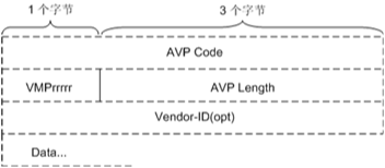
The fields are described as follows:
- AVP Code: 4 bytes. The AVP Code, combined with the Vendor-ID field, uniquely identifies the attribute. For example, the AVP Code of the Origin-Host is 264.
VMPrrrrr: 1 byte. The VMPrrrrr field indicates the AVP flags and instructs the receiver how to handle each attribute.
- V: 1 bit. The "V" bit indicates whether the Vendor-ID field is present in the AVP header. 1 indicates that the Vendor-ID field is present, and 0 indicates that the Vendor-ID field is not present.
- M: 1 bit. The "M" bit indicates whether support of the AVP is required. 1 indicates that support of the AVP is required, and 0 indicates that support of the AVP is not required.
- P: 1 bit. The "P" bit indicates whether the AVP data is encrypted. 1 indicates that the AVP data is encrypted, and 0 indicates that the AVP data is not encrypted.
- r: 5 bits. The "r" (reserved) bits are unused and should be set to 0.
- AVP Length: 3 bytes. This field indicates the number of bytes in the AVP, including the AVP Code, AVP Length, AVP Flags, Vendor-ID (if present), and AVP Data. Each AVP must be padded to align on a 4-byte boundary. A number of zero-valued bytes are added to the end of the AVP Data field until the boundary is reached.
- Vendor-ID (opt): 4 bytes. This field is present if the "V" bit is set in the VMPrrrrr field. The optional Vendor-ID field contains the IANA assigned "SMI Network Management Private Enterprise Codes" value of the vendor that generates the AVP value. The Vendor-ID value assigned to Huawei is 2011.
- Data: This field contains information specific to the AVP. The data type is determined by the AVP Code.
AVP Data Format
The Data field is zero or more bytes and contains information specific to the attribute. The format and length of the Data field is determined by the AVP Code and AVP Length fields. The format of the Data field must be one of the following data types, as shown in Table 1.
Data Type |
Description |
|---|---|
OctetString |
The data contains arbitrary data of variable length. Unless otherwise noted, the AVP Length field must be set to at least 8 bits (12 bits if the "V" bit is enabled). AVP values of this type that are not a multiple of four-bytes in length are followed by the necessary padding so that the next AVP (if any) will start on a 32-bit boundary. |
Integer32 |
32 bit signed value, transmitted in network byte order. The AVP Length field must be set to 12 bits (16 bits if the "V" bit is enabled). |
Integer64 |
64 bit signed value, transmitted in network byte order. The AVP Length field must be set to 16 bits (20 bits if the "V" bit is enabled). |
Unsigned32 |
32 bit unsigned value, transmitted in network byte order. The AVP Length field must be set to 12 bits (16 bits if the "V" bit is enabled). |
Unsigned64 |
64 bit unsigned value, transmitted in network byte order. The AVP Length field must be set to 16 bits (20 bits if the "V" bit is enabled). |
Float32 |
32 bit floating point value of single precision, transmitted in network byte order. The AVP Length field must be set to 12 bits (16 bits if the "V" bit is enabled). |
Float64 |
64 bit floating point value of double precision, transmitted in network byte order. The AVP Length field must be set to 16 bits (20 bits if the "V" bit is enabled). |
Grouped |
A sequence of AVPs. Each of these AVPs follows in the order in which they are specified, including their headers and padding. The AVP Length field is set to 8 bits (12 bits if the "V" bit is enabled) plus the total length of all included AVPs, including their headers and padding. Therefore, the AVP Length field of a Grouped AVP is always a multiple of 4 bytes. |
Address |
A string of numbers. The Address format is derived from the OctetString AVP Base Format. The first two bytes of the Address AVP represent the AddressType. The other bytes represent the address. The AddressType is used to discriminate the content and format of the remaining bytes. For example, the AddressType in the Address AVP can represent a 32-bit (IPv4) or 128-bit (IPv6) address. The Address AVP corresponds to the IPAddress defined in the online charging protocol (OCP). |
Time |
A string of numbers. The Time format is derived from the OctetString AVP Base Format. The string must contain four bytes, in the same format as the first four bytes in the Network Time Protocol (NTP) timestamp format. This represents the number of seconds since 00:00:00 on January 1, 1900 with respect to the Coordinated Universal Time (UTC). On 06:28:16 UTC, February 7, 2036, the time value will overflow. |
UTF8String |
An OctetString using the UTF-8 transformation format. |
DiameterIdentity |
The DiameterIdentity value is used to uniquely identify a Diameter node for duplicate connection and routing loop detection. DiameterIdentity is the same as the fully qualified domain name (FQDN) of the Diameter Credit-Control (DCC) node. |
Enumerated |
An enumerated type. The definition contains a list of valid values and their interpretation and is described in the Diameter application introducing the AVP. |
Gx Interface
A Gx interface is an application type of Diameter, which is used to implement policy control. Figure 3 shows the position of a Gx interface in the 3GPP architecture.
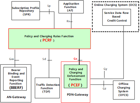
The PCRF formulates PCC rules based on the session information, user subscription information, and carrier policy information obtained from the AF and provides the PCC rules for the PCEF, the gateway on a packet switched network (PSN).
The PCEF is used to detect service data flows, obtains the service-based control and accounting policy from the PCRF, and implements the policy.
A Gx interface allows the communication between the PCEF and PCRF. In the 3GPP architecture, the NetEngine 8000 F implements functions of PCEF function entities and communicate with the PCRF through 3GPP-defined Diameter Gx interfaces.
Message Types of Gx Interfaces
Gx interface messages include CCR/CCA and RAR/RAA messages. Table 2 describes each type of Gx interface messages.
Name |
Direction |
Description |
|---|---|---|
CCR (Gx Message) |
PCEF -> PCRF |
When the PCEF communicates with the PCRF, the following CCR messages are used: CCR Initial request, CCR Update request, and CCR Termination request. The PCEF uses CCR messages to report user online and offline information and the remaining traffic or service time. |
CCA (Gx Message) |
PCRF -> PCEF |
An answer to a CCR message. After the PCRF receives a CCR message carrying information about implementing or releasing a policy from the PCEF, the PCRF replies to the PCEF with a CCA message. CCA messages are used to respond to the user online and offline reports. |
RAR (Gx Message) |
PCRF -> PCEF |
The PCRF sends an RAR message to the PCEF to modify, add, or delete a value-added service policy of user services. |
RAA (Gx Message) |
PCEF -> PCRF |
After the PCEF implements the new policy carried in an RAR message sent by the PCRF, the PCEF sends an RAA message to the PCRF to report the policy update. |
Message Exchanges on Gx Interfaces
The following describes message exchanges between the NetEngine 8000 F as the PCEF and the PCRF. Figure 4 shows a typical networking.
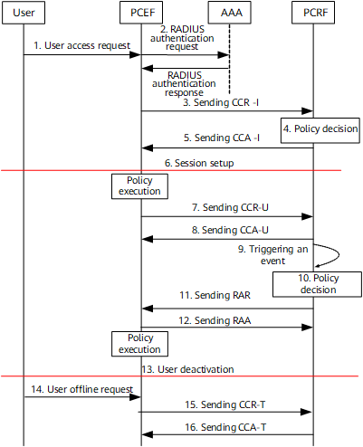
- A user sends a login request.
- (Optional) The RADIUS server authenticates the user and delivers a static user profile (Charging-Rule-Base-Name).
- The PCEF sends a credit control request (CCR-I) message to the PCRF to apply for a policy.
- The PCRF formulates a policy for a charging rule or QoS parameters.
- The PCRF sends a credit control answer (CCA-I) message carrying the policy to the PCEF. The policy includes a pre-defined rule, pre-defined rule group, or dynamic rule. The CCA message can also carry information about the user's remaining traffic or service time.
- The user session is established.
- The PCEF sends a CCR-U message to the PCRF to report the remaining traffic or service time.
- The PCRF updates the remaining service time or traffic and sends a CCA-U message carrying this information to the PCEF.
- An event is triggered on the PCRF. For example, the traffic reaches the threshold.
- The PCRF formulates a policy based on the event for a charging rule or QoS parameters.
- The PCRF sends a Re-Auth-Request (RAR) message carrying the new policy to the PCEF.
- The PCEF implements the new policy and sends a re-authentication answer (RAA) message to the PCRF.
- The user is deactivated.
- The user sends an offline request to the PCEF.
- The PCEF sends a CCR-T message to the PCRF to request for releasing the user session.
- The PCRF sends a CCA-T message to the PCEF to confirm the release of the user session.
For details about Gx interfaces, see Gx Interface Protocol.
Diameter Dual-Device Hot Backup
Diameter can be used in dual-device hot backup scenarios. As shown in Figure 5, if the master and slave PCEFs are connected to the same PCRF in the dual-device hot backup scenario and the master PCEF becomes faulty, services are automatically switched to the slave PCEF, ensuring Gx interaction between the PCEF and PCRF.
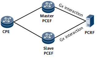
Figure 6 shows the interaction process in the Diameter dual-device hot backup scenario.
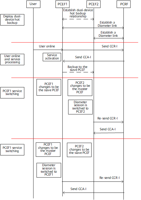
- Deploying dual-device hot backup: After dual-device hot backup deployed, establish two Diameter links, one between PCEF1 and the PCRF and the other between PCEF2 and the PCRF.
- User online and service processing: During service interaction, Diameter messages are sent and received on the master device (PCEF1), and the slave device (PCEF2) implements hot backup through RUI. The users on PCEF1 and PCEF2 use the same Session-Id AVP so that the interaction with the PCRF is not affected even when a service switchover occurs.
- Fault-triggered service switching on PCEF1: When PCEF1 becomes faulty and user services are switched to PCEF2, PCEF2 is changed to be the master device. PCEF2 retransmits CCR-I messages and instructs the PCRF to interact with PCEF2.
- Fault rectification on PCEF1: After the fault on PCEF1 is rectified, user traffic is switched back to PCEF1. The service switching process and service switchback process are the same.